α
2 Simple Application Controllers
AL2-2DA (AL2-14MR-*, AL2-24MR-*) 11
ENG-58
11.3.2 Wiring
Caution
• Turn off the Power before performing any wiring operations.
• The Output cables should not be run through the same multi core cable or share the
same wire.
• The wire should be used as a single cable or the multi core wires (can be used with a
crimp terminal) should be carefully twisted together.
Do not connect a soldered wire end to the
α2 Series Controller.
• The Output cable length must be less than 30 m (98' 5")
• To avoid damaging the wire, tighten to a torque of 0.5 - 0.6 N·m.
• The connectors must be covered to prevent contact with “Live” wires.
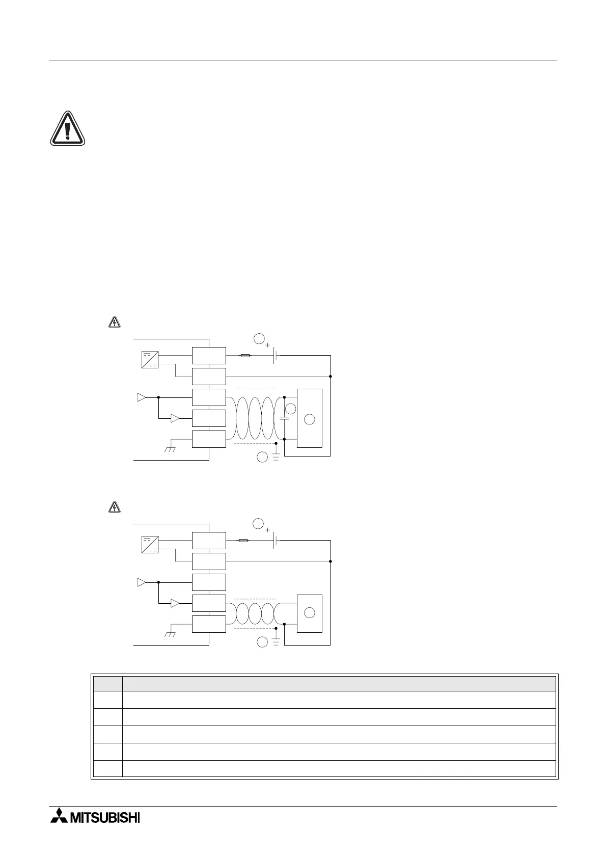
Figure 11.3:Wiring in Voltage output mode
Figure 11.4:Wiring in Current output mode
Table 11.5: Wiring Notation
Item Description
1 Grounding resistance of 100Ω or less
2 In the case of apparent excess noise please connect a 0.1-0.47μF capacitor
3 External equipment such as an Inverter, etc.
4 External 24VDC power supply
5 External equipment such as a Record meter, etc.
-
VO+
IO+
VIO-
+
24V DC
Note: "+" and "-" terminals are nonreversible.
AL2-2DA
DC/DC converter
4
2
3
1
1.0A
-
VO+
IO+
VIO-
+
24V DC
AL2-2DA
Note: "+" and "-" terminals are nonreversible.
DC/DC converter
1
5
4
1.0A

 Loading...


