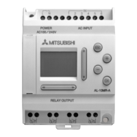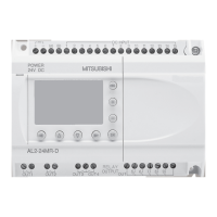
Do you have a question about the Mitsubishi Alpha Series and is the answer not in the manual?
| Power Supply | 100-240V AC |
|---|---|
| Programming Language | Ladder Diagram |
| Communication | RS-485 |
| Output Type | Relay or Transistor (depending on model) |
| Display | LCD |
| Storage Temperature | -20°C to 70°C |
Provides information on user safety and protection for Alpha controllers.
Explains the meaning of symbols used in the manual for warnings and notes.
Provides an overview of the Alpha Series controller's capabilities and applications.
Explains the five types of items used in function block programming and the FBD base.
Details the direct programming and software-based programming methods.
Describes the function and operation of the eight front panel keys.
Guides the user through navigating and using the Alpha's menus.
Explains the top menu options available when the Alpha is not running.
Details the top menu options accessible when the Alpha is running a program.
Describes the edit menu functions for program modification.
Explains how to edit individual function blocks.
Covers various system options like language and clock settings.
Explains the different types of data displayed on the LCD.
Describes the components of block items like input and function blocks.
Explains the pictorial representation of information flow in programming.
Details the number of inputs, outputs, and function blocks available.
Explains the process of connecting function blocks and other elements.
Describes how to disconnect connected blocks.
Outlines the methods for creating new function blocks.
Covers editing existing function blocks, including setup and renaming.
Explains how to navigate between different blocks in the program.
Describes how to use the front panel keys as program inputs.
Explains the use and function of system bits M01 to M05.
Provides a description and memory usage for each function block.
Details how to monitor and update function block values and outputs.
Explains the AND logic function and its truth table.
Explains the OR logic function and its truth table.
Explains the NOT logic function and its truth table.
Explains the XOR logic function and its truth table.
Explains the NAND logic function and its truth table.
Explains the NOR logic function and its truth table.
Explains how to express logic functions using equations.
Describes the SET/RESET latching block and its priorities.
Explains the PULSE block for generating single output pulses.
Describes the ALT block for alternating output states.
Explains the DELAY block for timing outputs.
Describes the ONE SHOT block for generating single pulses with priority options.
Explains the FLICKER block for patterned ON/OFF output signals.
Covers programming the TimeSW block for date or weekly schedules.
Explains the COUNTER block for counting input pulses.
Describes the UP/DOWN COUNTER block for counting in both directions.
Explains the COMPARE block for value comparison.
Describes the OFFSET block for adjusting analog input values.
Explains the DISPLAY block for showing information on the LCD.
Describes the ZONE COMPARE block for range checking.
Explains the Schmitt Trigger block for input value comparison.
Describes the Hour Meter block for tracking operating time.
Guides on setting initial program options before programming.
Shows a sample function block diagram for a program.
Details the steps for inputting a program using function blocks.
Explains how to set parameters for specific function blocks.
Describes how to exit the programming environment.


