Do you have a question about the Mitsubishi City Multi PEFY-P72NMHSU-E and is the answer not in the manual?
| Brand | Mitsubishi |
|---|---|
| Model | City Multi PEFY-P72NMHSU-E |
| Category | Air Conditioner |
| Language | English |
Explains warning and caution symbols used in the manual.
Important safety warnings for installation, operation, and maintenance.
Specific safety guidelines for handling R410A refrigerant and related components.
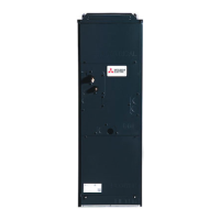
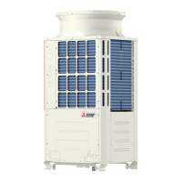
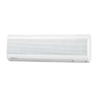
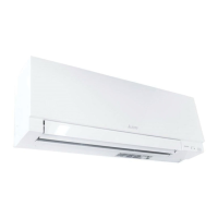
Description and illustration of the indoor unit and remote controller.
Explanation of the display elements on the remote controller.
Details technical specifications for units and electrical components.
Diagrams for sound measurement points and NC curves for PEFY-P72NMHSU-E.
NC curves for PEFY-P96NMHSU-E at various external static pressures.
Fan performance charts for PEFY-P72NMHSU-E at different static pressures.
Fan performance charts for PEFY-P96NMHSU-E at different static pressures.
Dimensional drawings and installation space requirements for the units.
Detailed wiring diagram for the indoor unit.
Schematic of the refrigerant system with labeled components.
Procedures for checking components like thermistors, fan motors, and expansion valves.
Table of error codes, definitions, and detection units.
Explanations for serial communication, drain, and motor related errors.
Details for various sensor, communication, and control errors.
Specific guidance for troubleshooting inverter and fan motor issues.
Steps for removing control box cover and intake air thermistor.
Procedure for removing thermistors, LEV, and drainpan.
Procedure for removing heat exchanger and reactor.
Procedure for removing fan motor and fan case.
List of part numbers for optional accessories like drain pump and filters.