Do you have a question about the Mitsubishi City Multi PURY-P400 and is the answer not in the manual?
| Series | City Multi |
|---|---|
| Refrigerant | R410A |
| Voltage (V) | 380-415 |
| Phase | 3 |
| Hertz (Hz) | 50 |
| Operating Temperature (Cooling) | -5 to +46°C |
Crucial safety guidelines for installation and electrical work, including warnings and precautions.
Explains the meaning of symbols used in the manual's text and illustrations for clarity.
Guidelines for selecting, storing, and preparing refrigerant piping to prevent contamination.
Rules for using tools, charging cylinders, and handling leaks with R407C refrigerant.
Instructions for proper indoor storage and sealing of piping materials before installation.
Proper oil application for flange connections to prevent refrigerant oil degradation.
Special care required during brazing to prevent contaminants from entering the refrigerant circuit.
Procedure for checking equipment airtightness using nitrogen and specific detectors.
Detailed steps for vacuuming the system and required equipment specifications.
Proper method for charging refrigerant in liquid state for non-azeotropic refrigerants.
Procedures for replacing the dryer and handling the refrigerant circuit.
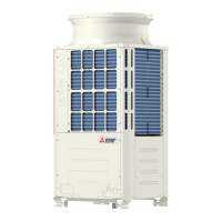
Visual identification and labeling of major outdoor unit components.
Table detailing standard operating data for the unit in cooling mode.
Details on DIP and rotary switch functions for the outdoor unit's operation.
Details on DIP switch functions for indoor units, including SW1 and SW3.
Essential checks and precautions to perform before initiating a test run.
Safety warnings and procedures for checking the inverter section due to high voltage.
Explanation of remote controller buttons and their functions for unit registration.
Step-by-step guide for registering indoor units with the remote controller.
Overview of the outdoor unit's control logic, including startup and capacity control.
Method for judging accumulator liquid level using temperature sensors and comparison.
Conditions and procedures for liquid level detection control, including prohibitions.
Control signals for SVA, SVB, and SVC based on operating mode and connection.
Control of SVM1 based on operation mode for FA type units.
Control of LEV opening based on operation mode, superheat, and differential pressure.
Flowchart detailing the outdoor unit's operation sequence and error handling.
Function, specification, and inspection method of the electronic expansion valve.
Function, specification, and inspection method of various thermistors.
Function, specification, and inspection method of the compressor.
Function and specifications of high and low pressure sensors.
Function and specifications of pressure switches.
Relationship between operating characteristics and the required refrigerant amount.
Methods for judging and adjusting refrigerant levels based on symptoms.
Troubleshooting guides for key unit components.
LEV operations, pulse signals, and troubleshooting for outdoor units.
Identifying and troubleshooting inverter-related defects and component failures.
Troubleshooting when the MA remote control indication goes off and the unit stops.
Troubleshooting when the M-NET remote controller "HO" display persists.
Identifies symptoms resulting from noise interference in the transmission line.
How to confirm transmission wave shape and voltage levels using an oscilloscope.
Flowchart for diagnosing and resolving pressure sensor issues in the BC controller.
Common LEV symptoms and methods for checking fully-open/closed status.
Procedure for removing the service panel to access internal components.
Procedure for accessing the control box and relay boards for inspection.
Comprehensive list of check codes and their corresponding error types.
Troubleshooting steps for mechanical errors based on specific check codes.
Troubleshooting for multiple address errors detected in communication.
Troubleshooting for transmission processor hardware errors.
Troubleshooting for errors related to exceeding the total capacity of indoor units.
Troubleshooting for errors related to incorrect capacity code settings.
Troubleshooting for errors when the connected unit count exceeds the limit.
Guide to interpreting LED indicators on the service monitor for operating conditions.
Steps for locating leaks in extension piping or indoor units during cooling mode.
Flowchart for checking and verifying the refrigerant composition and circulation.