Do you have a question about the Mitsubishi DY-6MW7U53-2 and is the answer not in the manual?
| Brand | Mitsubishi |
|---|---|
| Model | DY-6MW7U53-2 |
| Category | Car Receiver |
| Language | English |
Outlines radio capabilities such as preset functions, auto-store, tune control, RDS, and AM noise killer.
Details the 6-disc CD changer's functions like power load/eject, MP3 playback, and shockproof memory.
Describes audio section features including high power output, EQ adjustments, and sound customization.
Lists additional functions like beep sound, telephone mute, and steering remote control operation.
Provides frequency range, sensitivity, and S/N ratio for the AM (MW) band.
Details frequency range, separation, and S/N ratio for FM stereo reception.
Provides frequency range, sensitivity, and S/N ratio for the LW stereo band.
Lists dynamic range, S/N ratio, and channel separation for the CD changer.
Covers power supply, current consumption, output power, dimensions, and weight.
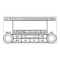
Explains button functions for radio mode, including tuning, presets, and mode changes.
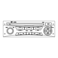
Details button functions for CD changer mode, covering disc handling and track selection.
Displays the station name received via RDS data.
Explains how to activate Traffic Program/Announcement and how TA information is displayed.
Allows searching for stations based on program type classification.
Enables selection of preferred language for PTY information.
Automatically selects the best receivable station within the same network.
Automatically receives emergency broadcasts when they occur.
Automatically adjusts the clock to local time using RDS time signals.
Lists pins and functions for the 18-pin Panel/Amp/AUX input connector.
Lists pins and functions for the 20-pin Power Supply/Speaker connector.
Illustrates the main components and their interconnections within the audio unit.
Shows how the main audio unit connects to antennas, speakers, and other vehicle systems.
Step-by-step guide to removing the unit's outer cover.
Instructions for removing the CDX3 unit and its associated cables.
Procedure for safely removing the heat sink assembly.
Steps to dismantle and remove front, left, and right chassis components.
Guide for unlatching and removing the main printed circuit board.
Visual representation of the unit's components in an exploded format.
Comprehensive list of parts with reference numbers, part numbers, and descriptions.
Explanation of SN74LVTH244APWR and SN74AHCT244PWR buffer ICs.
Details the LF33ABPT voltage regulator's function and pinout.
Explains the MM1185AFFE IC, likely a control or interface IC.
Details the M24C02 EEPROM for program storage.
Provides the circuit diagram for the NJM4580V operational amplifier.
Explains the AK7730AVT Sub-DSP, including its pinout and functions.
Details the SAA7709H audio processor's block diagram and pin functions.
Explains the TDA7563 power IC, including its circuit and pinout.
Lists chip resistors and capacitors with part numbers and values.
Provides a list of transistors with their part numbers and types.
Lists various diodes with their part numbers and descriptions.
Lists integrated circuits with part numbers and descriptions.
Lists coils with part numbers and descriptions.
Lists connectors with part numbers and descriptions.
Lists miscellaneous components like thermistors, crystals, and holders.
Shows the physical arrangement of components on the main PCB, parts side.
Illustrates the component layout on the main PCB, pattern side.
Detailed circuit diagram of the audio unit, Volume 1.
Detailed circuit diagram of the audio unit, Volume 2.
Detailed circuit diagram of the audio unit, Volume 3.
Detailed circuit diagram of the audio unit, Volume 4.
Lists pin voltages for the IC800 Audio μ-COM on the main PCB.
Lists pin voltages for the IC204 CDSP on the main PCB.
Lists pin voltages for the IC202 Sub DSP on the main PCB.
Lists pin voltages for the IC307 Power IC on the main PCB.
Shows voltage measurements for power supply related components on the main PCB.
Displays various signal waveforms for the IC800 µ-COM.
Shows signal waveforms for the IC204 CDSP.