INTAKE MANIFOLD
TSB Revision
INTAKE AND EXHAUST
15-12
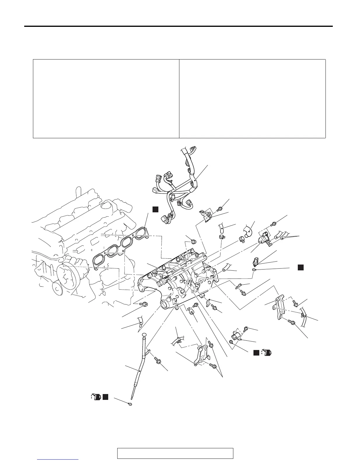
INTAKE MANIFOLD
REMOVAL AND INSTALLATION
M1151003002723
Pre-removal operation
• Engine Upper Cover Removal (Refer to GROUP 16, Igni-
tion System − Ignition Coil P.16-39).
• Air By-pass Valve, Air By-pass Hose, Charge Air Cooler
Intake Hose B Removal (Refer to
P.15-15).
• Air Cleaner Assembly Removal (Refer to P.15-10).
• Drive Belt Removal (Refer to GROUP 11A, Crankshaft
Pulley
P.11A-21).
• Throttle Body Removal (Refer to GROUP 13A, Throttle
Body
P.13A-918).
• Fuel Delivery Pipe and Fuel Injector Assembly Removal
(Refer to GROUP 13A, Injector
P.13A-914).
Post-installation operation
• Fuel Delivery Pipe and Fuel Injector Assembly Installation
(Refer to GROUP 13A, Injector
P.13A-914).
• Throttle Body Installation (Refer to GROUP 13A, Throttle
Body
P.13A-918).
• Air Cleaner Assembly Installation (Refer to P.15-10).
• Drive Belt Installation (Refer to GROUP 11A, Crankshaft
Pulley
P.11A-21).
• Air By-pass Valve, Air By-pass Hose, Charge Air Cooler
Intake Hose B Installation (Refer to
P.15-15)
• Engine Upper Cover Installation (Refer to GROUP 16,
Ignition System
− Ignition Coil P.16-39).
AC711118
5
3
2
6
18
15
1
19
N
10
17
20
8
13
12
N
9
(Engine oil)
21
20
AC
20
23 ± 6 N·m
17 ± 4 ft-lb
10 ± 2 N·m
89 ± 17 in-lb
23 ± 6 N·m
17 ± 4 ft-lb
23 ± 6 N·m
17 ± 4 ft-lb
23 ± 6 N·m
17 ± 4 ft-lb
8.0 ± 2.0 N·m
71 ± 18 in-lb
9.5 ± 2.5 N·m
35 ± 22 in-lb
5.0 ± 1.0 N·m
44 ± 9 in-lb
10 ± 2 N·m
89 ± 17 in-lb
10 ± 2 N·m
89 ± 17 in-lb
14 ± 1 N·m
120 ± 13 in-lb
10 ± 2 N·m
89 ± 17 in-lb
7
14
23 ± 6 N·m
17 ± 4 ft-lb
16
N
11
N
(Engine oil)
4
Removal steps
1. Rocker cover PCV hose
2. Emission control equipment
vacuum hose connection
3. Emission vacuum hose connection
4. Brake booster vacuum hose
connection
Removal steps (Continued)
 Loading...


