HEAD OFFICE : MITSUBISHI DENKI BLDG MARUNOUTI TOKYO 100-8310 TELEX : J24532 CABLE MELCO TOKYO
HIMEJI WORKS : 840, CHIYODA CHO, HIMEJI, JAPAN
7. ADJUSTMENT OF OFFSET AND GAIN
7.1 offset and gain
The offset value and the gain value when the factory is shipped are adjusted for a digital value to become 0
to 4000 for the voltage output 0 to 10V. It is necessary to readjust the offset value and the gain value when
FX
2N
-2DA is used by the current output, and FX
2N
-2DA is used by the output characteristics other than
shipping the factory. The adjustment of the offset value and the gain value sets a digital value to the
analogue value actually output by using the Voltmeter and the Ammeter according to the volume of FX
2N
-
2DA.
*1 A digital value increases if the volume installed in FX
2N
-2DA is turned right (clockwise).
7.1.1 Adjustment of gain
The gain value can be set to an arbitrary digital value.
However, to demonstrate the resolution of 12bit to its maximum, a digital range of 0 to 4000 is available.
A digital value is adjusted to 4000 at 10V in the analog output value when the voltage is output.
A digital value is adjusted to 4000 at 20mA in the analog output value when the current is output.
7.1.2 Adjustment of offset
The offset value when the voltage is input is 0V, and the offset value when the current is input is 4mA
fixation. However, the offset value/the gain value can be minute adjusted if necessary. Set at the following
when minute adjusting.
For instance, when a digital range of 0 to 4000 is used with the analogue range of 0 to 10V, a digital value
of 40 is equal to an analog output of 100mV, (40
×
10V/4000 digital points), when a digital range of 0 to
4000 is used with the analogue range of 4 to 20mA, a digital value of 0 is equal to an analog output of
4mA.
1) Do the offset adjustment and the gain adjustment respectively of CH1 and CH2.
2) Repeat the offset adjustment and gain adjustment alternately until a stable value is reached.
3) Do in order of the gain adjustment and the offset adjustment when you adjust offset/gain.
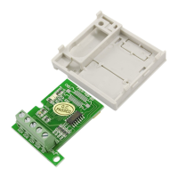
A
+
-
VOUT
IOUT
COM
FX
2N
-2DA
Ammeter
V
+
-
VOUT
IOUT
COM
FX
2N
-2DA
Voltmeter
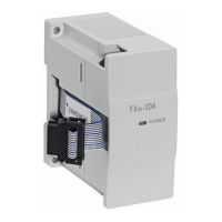
POWER
COM2
IOUT1
VOUT1
IOUT2
VOUT2
COM1
CH1
OFFSET
OFFSET
CH2
GAIN
CH1
CH2
GAIN
OFFSET
CH1
COM2
POWER
OFFSET
CH2
GAIN
CH1
CH2
GAIN
CH1
Offset volume
CH1
Gain volume
CH2
Offset volume
CH2
Gain volume
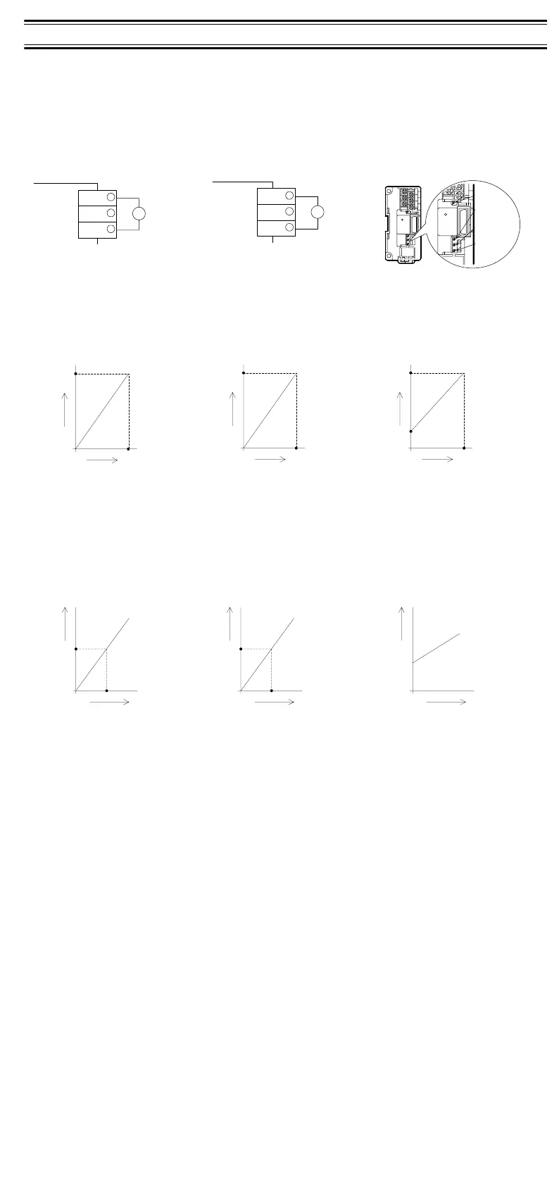
OUT2
Voltage output
urrent output
Volume *1
0 4000
10V
Voltage output
characteristic (0 to 10V)
Analog
value
Digital value
0 4000
5V
Voltage output
characteristic (0 to 5V)
Analog
value
Digital value
Voltage output
characteristic (4 to 20mA)
0 4000
20m
A
4mA
Analog
value
Digital value
Analogue
value
Digital value
040
100mV
Voltage output
characteristic (0 to 10V)
At factory is shipped
080
100mV
Voltage output
characteristic (0 to 5V)
Analogue
value
Digital value
Voltage output
characteristic (4 to 20mA)
0
4mA
Analogue
value
Digital value
8. PROGRAM EXAMPLE
The following program examples (8.1 and 8.2) are formula circuits.
The device numbers that have been underlined can be assigned by the user during programming.
8.1 At connection to FX
0N
series PLC
Digital to analog conversion execution input of CH1 :X000
Digital to analog conversion execution input of CH2 :X001
D/A output data CH1:D100 (Replace with auxiliary relay M100 to M131. Assign these numbers only one
time)
D/A output data CH2:D101 (Replace with auxiliary relay M100 to M131. Assign these numbers only one
time)
Processing time:Time until FX
2N
-2DA outputs analog value after turning on X000 and X001.
4mS / 1 channel
8.2 At connection to FX
1N
, FX
2N
or FX
2N
series PLC
Digital to analog conversion execution input of CH1 :X000
Digital to analog conversion execution input of CH2 :X001
D/A output data CH1:D100 (Replace with auxiliary relay M100 to M115. Assign these numbers only one
time)
D/A output data CH2 :D101 (Replace with auxiliary relay M100 to M115. Assign these numbers only one
time)
Processing time:Time until FX
2N
-2DA outputs analog value after turning on X000 and X001.
4ms / 1 channel
8.3 At connect to FX
2N
(V3.00 or later) or FX
2N
(V3.00 or later) series PLC
Please use FNC 177 (WR3A).
0
X000
[T0 K0 K16 K4M116 K1 ]
[T0 K0 K17 H0004 K1 ]
[T0 K0 K17 H0000 K1 ]
[M0V D100 K4M100 ]
[M0V K2M100 K2M116 ]
[M0V K2M108
K2M116 ]
[T0 K0 K17 H0002 K1 ]
[T0 K0 K16 K4M116
K1 ]
[T0 K0 K17 H0004 K1 ]
[M0V D101
K4M100 ]
[T0 K0 K17 H0000 K1 ]
[M0V K2M100
K2M116 ]
[M0V K2M108
K2M116 ]
[T0 K0 K17 H0000 K1 ]
[T0 K0 K16 K4M116
K1 ]
[T0 K0 K17 H0000 K1 ]
61
X001
a
b
c
d
e
g
h
i
j
k
l
m
n
[T0 K0 K16 K4M116 K1 ] f
[T0 K0 K17 H0001 K1 ]
a)Digital data (D100) is progressed to
supplementary relay (M100-M115).
b)The subordinate position 8 bit data
is moved.
c)The subordinate position 8 bit data is
written.
d)The subordinate position 8 bit data is
held.
e)The high rank 4 bit data is moved.
f) The high rank 4 bit data is written.
g)The D/A conversion of CH1 is
executed.
h) Digital data (D101) is progressed to
supplementary relay (M100-M115).
i) The subordinate position 8 bit data is
moved.
j) The subordinate position 8 bit data is
written.
k)The subordinate position 8 bit data is
held.
l) The high rank 4 bit data is moved.
m)The high rank 4 bit data is written.
n)The D/A conversion of CH2 is
executed.
0
X000
[T0 K0 K17 H0004 K1 ]
51
X001
[T0 K0 K16 K1M108 K1 ]
[T0 K0 K17 H0000 K1 ]
[T0 K0 K17 H0000 K1 ]
[T0 K0 K17 H0004 K1 ]
[T0 K0 K16 K1M108 K1 ]
[T0 K0 K17 H0000 K1 ]
[T0 K0 K17 H0000 K1 ]
[T0 K0 K16 K2M100 K1 ]
[M0V D100
K4M100 ]
b
c
[T0 K0 K16 K2M100
K1 ]
[M0V D101
K4M100 ]
a
e
i
d
g
h
f
j
[T0 K0 K17 H0002 K1 ]
[T0 K0 K17 H0001 K1 ]
a)Digital data (D100) is progressed to
supplementary relay (M100-M115).
b)The subordinate position 8 bit data
is written.
c)The subordinate position 8 bit data
is held.
d)The high rank 4 bit data is written.
e )The D/A conversion of CH1 is
executed.
f) Digital data (D101) is progressed to
supplementary relay (M100-M115).
g)The subordinate position 8 bit data
is written.
h)The subordinate position 8 bit data
is held.
i) The high rank 4 bit data is written.
j) The D/A conversion of CH2 is
executed.
9. NOTES IN DRIVE
1) Confirm whether the output wiring of FX
2N
-2DA and the connection of the extension cable are
correctly done.
2) Confirm whether the "4.
Connection with programmable controller" condition is satisfied.
3) When shipped from the factory, the output characteristic is adjusted to 0 to 10V DC.
If a different output characteristic is desired, please adjust as required.
4) The mixture use for the voltage output/the current output is possible.
10. ERROR CHECK
Confirm the following items when it is thought that the FX
2N
-2DA does not operate normally.
1) Confirm the state of POWER LED.
Lit :The extension cable is correctly connected.
Turn off or blinks :Confirm the proper connection of the extension cable.
2) Confirm whether it is external wiring per section 3.
3) Confirm whether the load resistance of the equipment connected with an analog output terminal is the
one corresponding to FX
2N
-2DA.
4) Confirm the voltage and output Current values with a voltmeter and an ammeter. Confirm the digital to
analog conversion from the output characteristic. Readjust the offset and gain by "Change and
adjustment method of the output characteristic" when you have converted D/A not suitable for the
output characteristic. The output characteristic when shipped from the factory is DC0-10V.
Guidelines for the safety of the user and protection of the FX
2N
-2DA SPECIAL
FUNCTION BLOCK
• This manual has been written to be used by trained and competent personnel. This is defined
by the European directives for machinery, low voltage and EMC.
• If in doubt at any stage during the installation of the FX
2N
-2DA always consult a professional
electrical engineer who is qualified and trained to the local and national standards. If in doubt
about the operation or use of the FX
2N
-2DA please consult the nearest Mitsubishi Electric
distributor.
• Under no circumstances will Mitsubishi Electric be liable or responsible for any consequential
damage that may arise as a result of the installation or use of this equipment.
• All examples and diagrams shown in this manual are intended only as an aid to
understanding the text, not to guarantee operation. Mitsubishi Electric will accept no
responsibility for actual use of the product based on these illustrative examples.
• Owing to the very great variety in possible application of this equipment, you must satisfy
yourself as to its suitability for your specific application.
Manual number : JY992D74901
Manual revision: C
Date : April 2001
JY992D74901C
Effective APRIL 2001
Specifications are subject to
change without notice
 Loading...