TROUBLESHOOTING
ENGINE COOLING
14-6
TECHNICAL DESCRIPTION
• The cause could be a malfunction of the fan con-
troller power supply or earth circuit.
• The cause could also be a malfunction of the fan
controller or the engine-ECU.
TROUBLESHOOTING HINTS
• Malfunction of fusible link
• Malfunction of fan control relay
• Malfunction of cooling fan motor
• Malfunction of fan controller
• Malfunction of engine-ECU
• Damaged wiring harness or connector
DIAGNOSIS
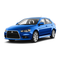
STEP 1. Check the circuit at fan controller
connector A-17 terminal 3.
AC210859
Connector: A-17
A-17 (GR)
AD
Fan controller
Component side
(1) Disconnect fan controller connector A-17, and
measure at the harness side connector.
(2) Measure the voltage between terminal No.3 and
earth.
• When the ignition switch is turned to the "ON"
position, voltage should measure battery pos
-
itive voltage.
Q: Is the voltage battery positive voltage when the
ignition switch is turned to the "ON" position?
YES : Go to Step 7.
NO : Go to Step 2.
STEP 2. Check the fan control relay.
Refer to P.14-17.
Q: Is the fan control relay in good condition?
YES : Go to Step 3.
NO : Replace it, then go to Step 1.
STEP 3. Check for harness damage between
fusible link No.2 and fan control relay connector
A-09X terminal 4.
AC310900
AC
Fusible link (2)
Fusible link (2) And
Connector: A-09X
A-09X
3
1
4
2
Relay box
side
Q: Are the harness wires between fusible link No.2
and fan control relay connector A-09X damaged?
YES : Repair or replace them, then go to Step 13.
NO : Go to Step 4.
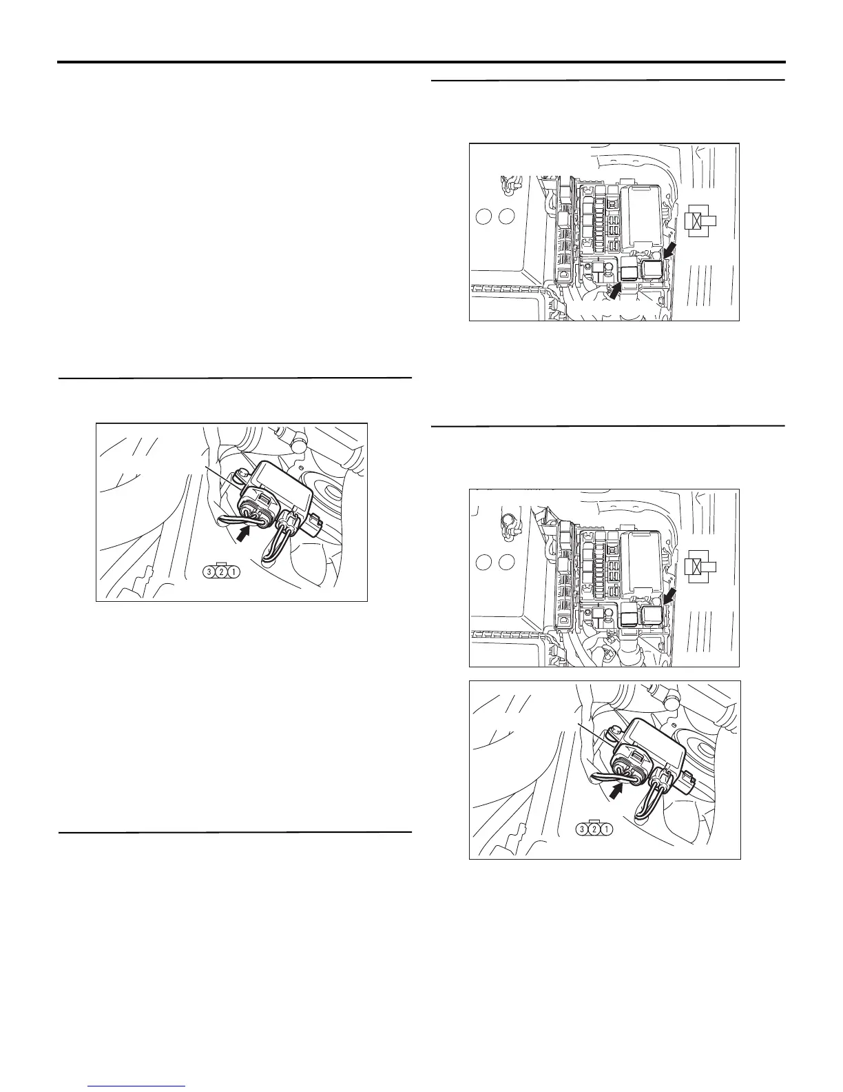
STEP 4. Check for harness damage between fan
control relay connector A-09X terminal 2 and fan
controller connector A-17 terminal 3.
AC310900
AB
Connector: A-09X
A-09X
3
1
4
2
Relay box
side
AC210859
Connector: A-17
A-17 (GR)
AD
Fan controller
Component side
Q: Are the harness wires between fan control relay
connector A-09X terminal 2 and fan controller
connector A-17 terminal 3 damaged?
YES : Repair or replace them, then go to Step 13.
NO : Go to Step 5.
 Loading...