GB-7
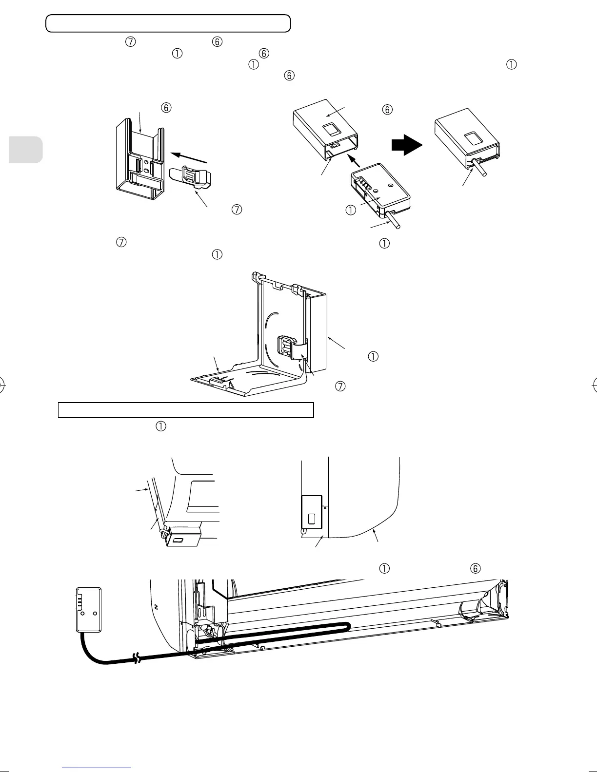
Runtheconnectingcableinthespaceonthebackoftheunitasshownintheabovegure.
Tuckcablingawayandsecureit.
Note:Makesurethattheconnectingcablewillnotgetcaughtonorbetweentheinstallationplateand
thewall,orbetweentheindoorunitandtheinstallationplate.
Failuretodosomaycausedamagetotheconnectingcableresultingincommunicationproblems.
• Sliptheclip overtheedgeofcornerboxtoxtheinterfaceunit .
Note:Mount the interface unit on the underside of the indoor unit if it cannot be
mountedonthesideoftheindoorunit.
Interface
unit
Cornerbox
Clip
Indoorunit
Indoorunit
• TochecktheLEDindicationaftersetup,removetheinterfaceunit
fromtheholder .
Exampleofmountingontheleftsideofindoorunit
Cornerbox
Cornerbox
Note:Interfaceunit
canalsobemountedontherightsideoftheindoorunit.
UndersideoftheIndoorunit
SideoftheIndoorunit
• Inserttheclip intotheholder untilitclicks.
• Inserttheinterfaceunit
intotheholder untilitclicks.
Note:Wheninsertingtheinterfaceunit intotheholder,alignthecableoftheInterfaceunit
withthemarkforthecableontheholder .
Otherwise,lightleakageordegradationinappearancemayresult.
Interfaceunit
Markforcable
Align
Clip
Holder
Holder
Connectingcable
Whenmountingontheoutersideofindoorunit
JG79Y198H01_01_en.indd 7 11/24/2016 10:35:10 AM