GB-6
4. Connecting the Wi-Fi interface
(For details on each system, see the relevant instruction manual.)
TurnoffthebreakeroftheroomairconditionerortheATWunitbeforeconnectingthecabletothe
indoorunit.
Refertotheinstallationmanualofeachmodelforconnectinginstructionsanddetails.
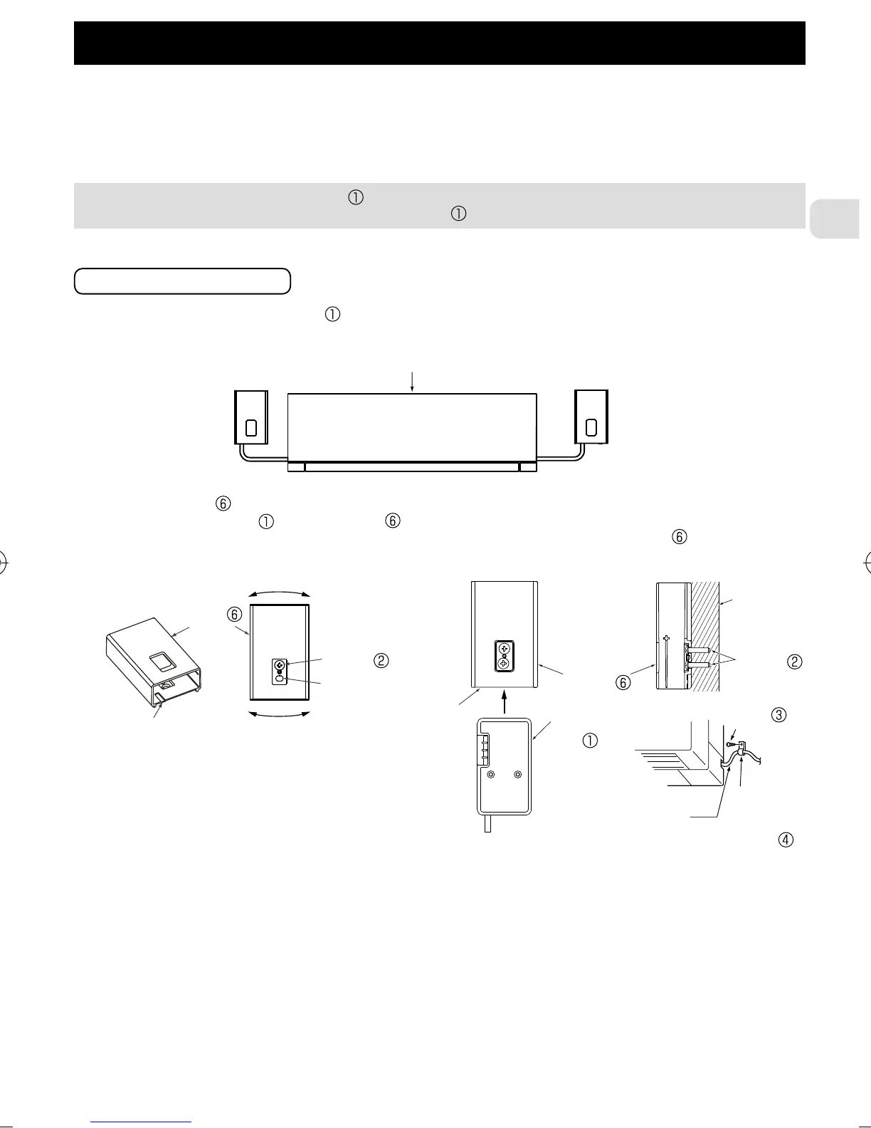
(1)Theconnectingcableconnectedtoaindoorunit(CN105)shouldbemountedattheindoorunitor
itsvicinity.
Takenoutfrom
theleftside
Indoorunit
<Roomairconditioner>
Takenoutfrom
therightside
When mounting the Interface unit inside an indoor unit, refer to the installation manual of
the indoor unit. Do not mount the Interface unit inside the indoor unit, if not mentioned.
Markforcable
Markfor
cable
Interface
unit
Screw
Wall
Holder
Screw x
Adjustment
Holder
Thecablesideoftheinterfaceunit shouldfacedownward.
• Mounttheholder
onthewallsoitsmarkforthecablefacesdownward.
• Inserttheinterfaceunit
intotheholder untilitclicks.
Note:Tightentheupperandthenthelowerscrews;adjustandleveltheholder usingthe
elongatedholeforthelowerscrew.
Whenmountingonthewall
Mount-
ingcord
clamp
Screw
Connecting
cable
JG79Y198H01_01_en.indd 6 11/24/2016 10:35:09 AM