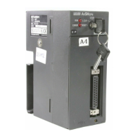
Do you have a question about the Mitsubishi MELSEC A1SCPU and is the answer not in the manual?
Introduces the Mitsubishi AIS programmable logic controller.
Explains the sequential control program execution and system operation.
Guides users on selecting appropriate input, output, and function modules.
Provides instructions for installing the PLC system.
Addresses the ease of programming and programming modes.
Lists example applications and the general purpose of the A1S PLC.
Details the CPU module, its functions, and specifications.
Explains the purpose and types of CPU base units.
Explains the purpose and types of extension base units.
Explains the function and types of power supply modules.
Introduces input modules and their interface function.
Introduces output modules and their interface function.
Introduces special function modules for dedicated control.
Introduces memory modules for program storage.
Introduces extension cables for connecting base units.
Introduces terminal block units and cables for connection.
Introduces the process of selecting the appropriate PLC system components.
Provides a flowchart for selecting the correct input modules.
Provides a flowchart for selecting the correct output modules.
Provides a flowchart for selecting special function modules.
Provides a flowchart for selecting the correct power supply module.
Provides a flowchart for selecting the correct base unit.
Explains how to configure the system and assign I/O numbers.
Presents example system configurations for various applications.
Lists unsuitable environments for PLC installation.
Provides instructions for mounting CPU and extension base units.
Explains the process of fixing base units to a DIN rail.
Details the procedure for removing base units from a DIN rail.
Explains how to install and remove A1S modules from the base unit.
Describes how to install and remove dustproof covers for extension base units.
Provides wiring guidelines for power supply modules.
Offers wiring instructions for connected input and output equipment.
Explains the proper grounding procedures for the PLC system.
Details PLC internal devices like inputs, outputs, relays, timers, counters, and registers.
Covers programming languages, numeric, and character representations.
Introduces categories of PLC instructions: Sequence, Basic, and Application.
Example of a MELSECNET/B data link control system.
Example of a positioning control system application.
Example of a robot control system application.
Example of an analog control system application.
Example of a sequence control system application.
| CPU Type | A1SCPU |
|---|---|
| Number of I/O Points | Up to 256 |
| Operating Temperature | 0 to 55°C |
| Program Capacity | 8K steps |
| Number of Timers | 256 |
| Number of Counters | 256 |
| Programming Language | Ladder Diagram, Structured Text |
| Communication Protocols | RS-422 |
| Power Supply | 24V DC |
| Program Memory | RAM |
| Storage Temperature | -25°C to 65°C |
| Humidity | 5 to 95% (non-condensing) |
| Shock Resistance | 150 m/s² |
| Type | Programmable Logic Controller (PLC) |


