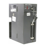
Do you have a question about the Mitsubishi MELSEC-A A1SHCPU and is the answer not in the manual?
Precautions related to the design of the system and circuits for safe operation.
Precautions to be observed during the installation process to ensure safety.
Precautions related to electrical wiring and connections for safe operation.
Precautions for initial startup and ongoing maintenance procedures.
Safety and operational guidelines for various power supply modules.
Notes and torque specifications for installing various modules.
Examples of system designs illustrating fail-safe circuit implementation.
Step-by-step procedures for switching on the power supply in AC and AC/DC systems.
Measures to prevent system failure and accidents due to controller malfunctions.
Instructions for wiring power supply cables and I/O cables correctly.
Diagnostic procedure for verifying the A1SCPUC24-R2 communication.
Specifications for various input modules, including voltage, current, and response time.
Wiring diagrams for connecting different types of input modules.
Guide on how to read and interpret error codes reported by the system.
List of error messages, codes, causes, and corrective actions for A1SCPUC24-R2.
List of error messages, codes, causes, and corrective actions for A1SHCPU/A2SHCPU.
List of error messages, codes, causes, and corrective actions for A2ASCPU/A2USHCPU-S1.
| Type | Programmable Logic Controller (PLC) |
|---|---|
| Model | A1SHCPU |
| Program Capacity | 14K steps |
| I/O Points | 256 points |
| Operating Temperature | 0 to 55°C |
| Basic Instruction Execution Time | 0.2 μs |
| Memory Type | RAM |
| Built-in Communication Ports | RS-232 |
| Power Supply | 24V DC |
| Storage Temperature | -25°C to 75°C |
| Humidity | 5 to 95% RH (non-condensing) |
| Vibration Resistance | 10 to 57 Hz |


 Loading...