Do you have a question about the Mitsubishi MELSEC-A series and is the answer not in the manual?
Explains the AD71 operating principles, glossary of terms, and MELSEC-A series system configurations.
Shows a schematic diagram of MELSEC-A series equipment for use with the AD71.
Details the available equipment for programming the AD71, including software and hardware.
Details general specifications such as operating ambient temperature, humidity, vibration, and shock resistance.
Outlines AD71 performance specifications like I/O points, control axes, interpolation, and available functions.
Explains AD71 interfaces and the PC-initiated positioning procedure.
Describes parameters, zeroing data, and positioning data required for AD71 operation.
Details the AD71's battery-backed buffer memory for PC CPU data communication.
Lists and explains I/O signals for non-numerical communication between the AD71 and PC CPU.
Provides electrical specifications for AD71 I/O interfaces with external equipment.
Details the specifications of the AGBAT battery used for AD71 memory backup.
Provides guidelines for protecting the AD71 from mechanical shock, debris, and proper connection procedures.
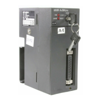
Identifies and explains the labels, LEDs, connectors, and switches on the AD71 unit.
Covers preparation steps, specifically focusing on battery connection and static electricity precautions.
Specifies unsuitable installation environments for the AD71 equipment.
Outlines precautions for system design, including base unit usage and panel temperature control.
Details the procedure for installing and removing the AD71 unit from the base unit.
Provides essential precautions for wiring, including cable length and I/O signal routing in noisy environments.
Explains program structure for A6GPP, AD71TU, and sequence program operations.
Notes on using external programming units, including operational conditions and data transfer.
Details how to initiate a positioning operation, simplifying it by pre-loading data into the buffer memory.
Explains the program flow and conditions for controlling motor movement using jog operation.
Describes the operating principle of manual pulser inching, including pulse conversion and speed control.
Outlines the zeroing process, including flowcharts, conditions, and timing for system setup.
Explains how to stop the positioning process while the AD71 is busy using various stop signals.
Explains programming for remote I/O stations, including data communication and control signals.
Lists essential checks before testing the AD71, including battery, parameters, and data settings.
Outlines procedures for sequence checks and verifying positioning operation with the system.
Details error detection mechanisms, error codes, and procedures for resetting errors in the AD71.
Provides flowcharts for diagnosing and resolving common issues like drive problems, incorrect positioning, and speed errors.
Specifies recommended storage environments and handling for the AD71 unit.
Details battery change frequency, handling, and replacement procedures for memory backup.
Provides format sheets and detailed parameter lists for AD71 configuration.
Illustrates AD71 processing times for pattern operations, excluding PC operating time.
Offers system design considerations and connection diagrams for various servo motors and external equipment.
Provides connection diagrams for servo motors and external equipment like pulse motors and position units.
Shows the physical dimensions of the AD71 unit.
Contains tables for converting positioning data numbers to buffer memory addresses.
| Type | Programmable Logic Controller (PLC) |
|---|---|
| Series | MELSEC-A |
| I/O Capacity | Varies depending on the CPU and expansion modules used. |
| I/O Points | Varies depending on the CPU and expansion modules used. |
| Programming Language | Instruction List |
| Program Memory | Varies by model |
| Data Memory | Varies by model |
| Communication Protocols | MELSECNET |
| Communication Ports | Varies by model |
| Power Supply | AC 100-240V, DC 24V (varies by model) |
| Expansion Modules | Available (varies by model) |
| I/O Modules | Digital, Analog |
| Memory | RAM, EEPROM |
| Operating Temperature | 0°C to 55°C |
| Storage Temperature | -25°C to 75°C |
| Humidity | 5 to 95% RH, non-condensing |
| Vibration Resistance | 10 to 57Hz: 0.075mm amplitude, 57 to 150Hz: 9.8m/s² |


