3.
SPECWICATIONS
/MELSEC-A
3.3
Positioning
System Operation
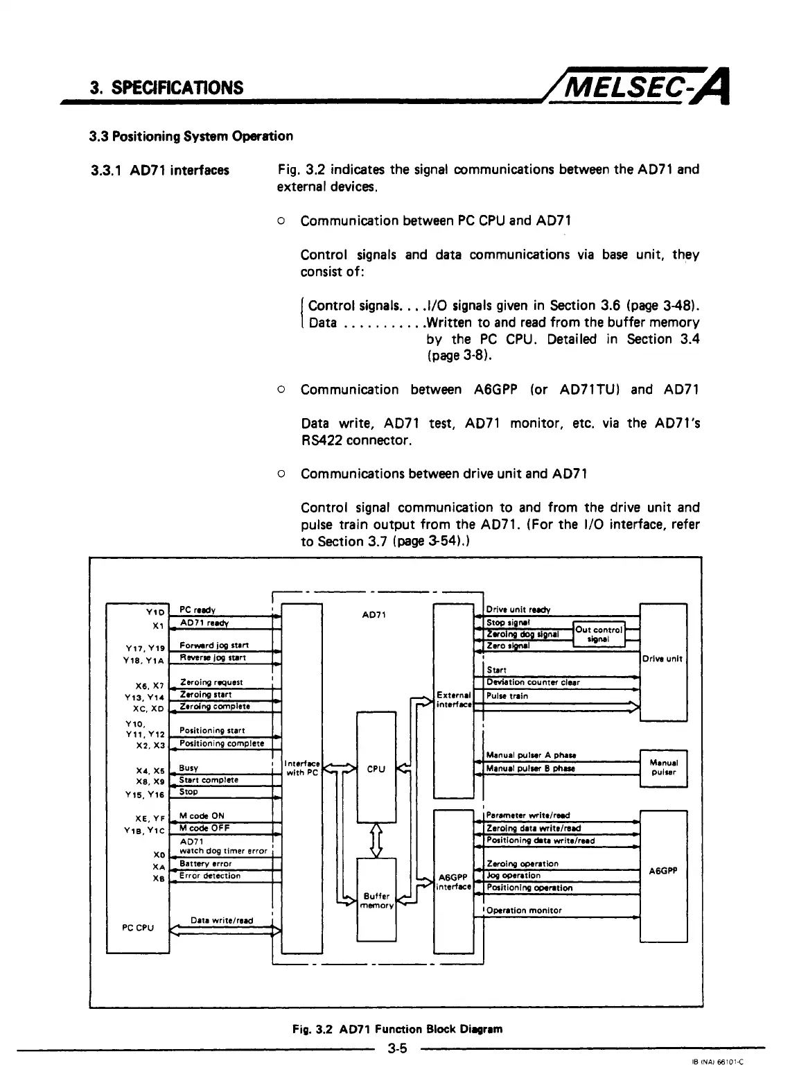
3.3.1
AD71
interfaces Fig, 3.2 indicates the signal communications between
the
AD71
and
external devices.
o
Communication between
PC
CPU and AD71
Control signals and data communications
via
base unit, they
consist of:
I
Control signals.
.
,
.I/O signals given in Section 3.6
(page
348).
Data
. . .
.
.
.
.
.
. .
.Written to and read from the buffer memory
by the
PC
CPU. Detailed in Section 3.4
(page
3-81.
0
Communication between A6GPP (or AD71TU) and AD71
Data write, AD71
test,
AD71 monitor,
etc. via
the AD7l's
RS422
connector.
o
Communications between drive unit and AD71
Control signal communication to and from the drive unit and
pulse train output from the AD71. (For the
1/0
interface, refer
to Section 3.7
(page
3-54).]
PC
CPU
Data writelread
I
II-
-1
Fig.
3.2
AD71
Function
Block Diagram
3-5
IB
INAl
€6101-C
c
L
c
r
I

 Loading...


