3.
SPECIFICATIONS
/MELSEC-A
3.7
I/O
interface with External Equipment
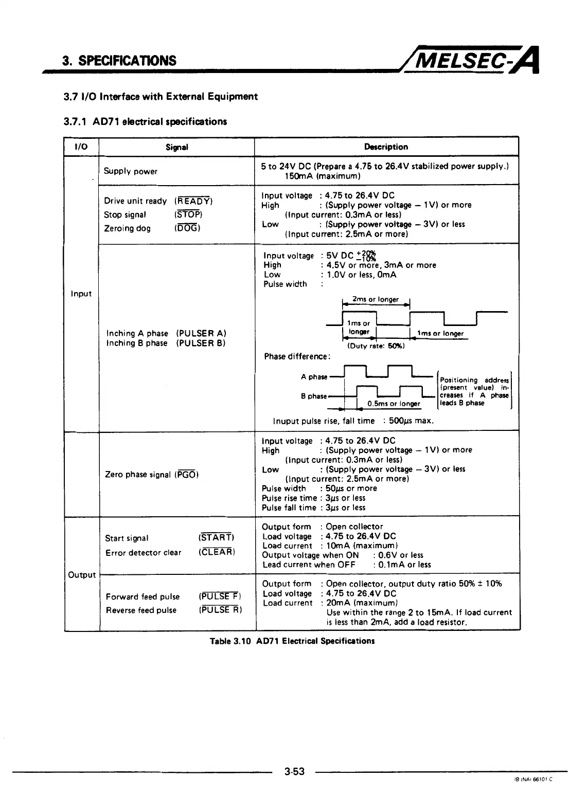
3.7.1 AD71 electrical specifications
Signal
Supply power
Drive unit ready (READY)
Stop signal
(STOP)
Zeroing dog
(DOG)
Inching A phase
(PULSER
A)
Inching
B
phase (PULSER
6)
Zero phase signal
(m)
Start
signal
(START)
Error detector clear
(CLEAR)
Forward feed pulse
(-1
Reverse feed pulse
(m
1
~~
Description
5 to 24V DC (Prepare
a
4.75 to 26.4V stabilized power supply.)
150mA (maximum)
Input voltage
:
4.75 to 26.4V DC
High
:
(Supply power voltage
-
1
V) or more
(Input current: 0.3mA or
less)
(Input current: 2.5mA or more)
Low
:
(Supply power
voltage
-
3V) or
less
Input voltage
:
5V DC
if@
High
:
4.5V
or
more, 3mA or more
Low
:
1
.OV or
less,
OmA
Pulse width
:
2ms or
longer
-
I
lrnr
or
lonmr
(Duty
rate:
lmr
or
longer
I
-
-
Phase difference:
----
B
phase
creases
!;::$?
if
A
phase
lnuput pulse rise, fall time
:
500~s max.
Input voltage
:
4.75 to 26.4V DC
High
:
(Supply power voltage
-
1
V) or more
(Input current: 0.3mA or
less)
(Input current: 2.5mA or more)
Low
:
(Supply power voltage
-
3V) or
less
Pulse
width
:
50p
or more
Pulse
rise time
:
3~s or
less
Pulse fall time
:
3~s or
less
Output form
:
Open collector
Load voltage
:
4.75 to 26.4V DC
Load current
:
lOmA (maximum)
Output voltage when
ON
:
0.6V or
less
Lead current when OFF
:
O.lmA or
less
Output form
:
Open collector, output duty ratio
50%
f
10%
Load voltage
:
4.75 to 26.4V DC
Load current
:
20mA (maximum)
~~ ~ ~ ~~
Use within
the
range
2
to 15mA. If load current
is
less
than 2mA. add
a
load resistor.
i
t
I
TaMe
3.10
AD71
Electrical Specifications
b
t
4
3-53
4
IE
INAl
66101
C
1
I
 Loading...


