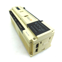
Do you have a question about the Mitsubishi MELSEC and is the answer not in the manual?
Details the technical specifications of the Base Unit.
Identifies and describes the physical parts of the Base Unit.
Information regarding the Q6BAT battery, including specifications and installation.
Outlines the steps to follow before operating the CPU module in SAFETY MODE.
Covers fundamental principles for locating and resolving system troubles.
Presents flowcharts for diagnosing and resolving specific operational problems.
Details various error codes, their causes, and corrective actions for system errors.
Highlights the new and key features of the QS series CPU module.
Provides instructions on how to identify the module's serial number and function version.
Describes the typical system configurations and components for the safety PLC.
Explains how to confirm the serial number and function version of the CPU module.
Details the performance characteristics and technical specifications of the CPU module.
Identifies and explains the various parts and indicators on the CPU module.
Describes the operation of switches after writing programs to the CPU module.
Explains the procedure for performing a reset operation on the CPU module.
Lists the technical specifications for the power supply modules.
Provides crucial precautions for connecting an uninterruptible power supply (UPS).
Details the technical specifications of the Base Unit.
Identifies and describes the physical parts of the Base Unit.
Information regarding the Q6BAT battery, including specifications and installation.
Outlines the steps to follow before operating the CPU module in SAFETY MODE.
Details the requirements and standards for conforming to the EMC Directive.
Outlines the requirements for conforming to the Low Voltage Directive.
Explains how to calculate heat generation within the PLC system for panel design.
Provides instructions and precautions for installing modules onto the base unit.
Lists important precautions to follow during module installation.
Details the correct procedures for mounting the base unit into an enclosure.
Explains the step-by-step process for installing and removing modules.
Covers essential precautions and procedures for wiring the PLC system components.
Lists critical safety precautions and guidelines for wiring the system.
Outlines the daily checks required to maintain the PLC system's condition.
Details the inspections to be performed at regular intervals (e.g., 6 months to 1 year).
Provides information on battery life and the procedure for replacing the CPU module battery.
Covers fundamental principles for locating and resolving system troubles.
Presents flowcharts for diagnosing and resolving specific operational problems.
Details various error codes, their causes, and corrective actions for system errors.
Provides external dimension drawings for the main hardware components.
Details additional functions and availability based on GX Developer versions.
Outlines regulations and precautions for transporting lithium batteries.
Provides guidance on disposal and export of batteries within EU member states.
| Category | Programmable Logic Controller (PLC) |
|---|---|
| Manufacturer | Mitsubishi Electric |
| Series | MELSEC |
| Programming Languages | Ladder Diagram (LD), Function Block Diagram (FBD), Structured Text (ST), Instruction List (IL), Sequential Function Chart (SFC) |
| Communication Protocols | Ethernet, CC-Link, RS-232, RS-485, USB, Profibus, Modbus |
| Model Series | FX, Q, L, iQ-R, iQ-F |
| Input Voltage | 100-240V AC, 24V DC (varies by model) |
| Memory Capacity | Varies widely depending on the CPU module and series. Ranges from kilobytes to megabytes. |
| I/O Points | 16 to 8192 points (varies by model) |
| Communication Ports | Ethernet, RS-232, RS-485, USB (varies by model) |
| Programming Software | GX Works2, GX Works3, GX Developer |
| Operating Temperature | 0°C to 55°C |
| Storage Temperature | -25°C to 75°C |
| Humidity | 5% to 95% (non-condensing) |
| Vibration Resistance | 10 to 57Hz, 0.075mm amplitude; 57 to 150Hz, 9.8m/s² acceleration |
| Shock Resistance | 147m/s², 3 times in each direction (X, Y, Z) |
| Protection Class | IP20 (varies by model) |
| CPU Processing Speed | 0.02μs to 0.1μs per instruction (varies by model) |


