11
MAINTENANCE AND INSPECTION
11.1 Daily Inspection
11 - 3
9
EMC AND LOW
VOLTAGE
DIRECTIVES
10
LOADING AND
INSTALLATION
11
MAINTENANCE AND
INSPECTION
12
TROUBLESHOOTING APPENDICES INDEX
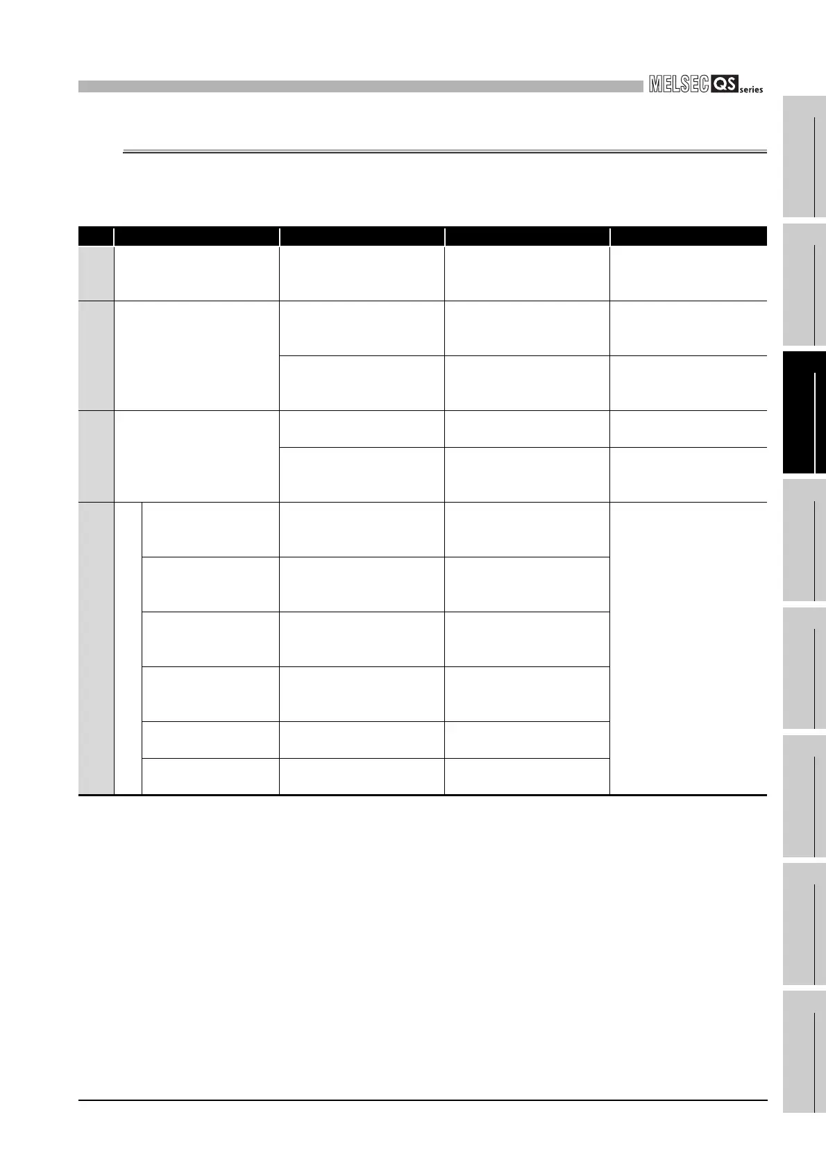
11.1 Daily Inspection
The items that must be inspected daily are listed in Table11.1.
*1: Normal operation indicates the following conditions.
Table11.1 Daily inspection
Item Inspection Item Inspection Judgment Criteria Remedy
1 Installation of base unit
Check that fixing screws are
not loose and the cover is
not dislocated.
The screws and cover must
be installed securely
Retighten the screws.
2
Installation of power supply
module and CPU module
Check that the module is not
dislocated and the unit fixing
hook is engaged securely.
The module fixing hook
must be engaged and
installed securely.
Securely engaged the unit
fixing hook.
Check that the module fixing
screws are securely
tightened.
The module fixing screws
must be securely tightened.
Securely tighten the
module fixing screws.
3 Connecting conditions
Check for loose terminal
screws.
Screws should not be loose.
Retighten the terminal
screws.
Check for distance between
solderless terminals.
The proper clearance
should be provided between
Solderless terminals.
Correct.
4
Module indication LED
Power supply module
"POWER" LED
Check that the LED is On
(green).
The LED must be On
(green).
(Abnormal if the LED is Off.)
Since the status other
than indicated on the
left is in the status other
than normal operation
*1
,
perform the
troubleshooting
referring to Section
12.2.
CPU module "ALIVE"
LED
Check that the LED is On
(green).
The LED must be On
(green).
(Abnormal if the LED is Off.)
CPU module "RUN"
LED
Check that the LED is On
(green).
The LED must be On
(green).
(Abnormal if the LED is Off.)
CPU module "ERR."
LED
Check that the LED is Off.
The LED must be Off.
(Abnormal if the LED is On
or flashing.)
CPU module "TEST"
LED
Check that the LED is Off.
The LED must be Off.
(Abnormal if the LED is On.)
CPU module "BAT."
LED
Check that the LED is Off.
The LED must be Off.
(Abnormal if the LED is On.)
• Safety CPU operation mode is in the SAFETY MODE.
• The CPU operation status is in the RUN status.

 Loading...

