12
TROUBLESHOOTING
12.2 Troubleshooting Flowchart
12.2.11 Flowchart for when a program cannot be written
12 - 17
9
EMC AND LOW
VOLTAGE
DIRECTIVES
10
LOADING AND
INSTALLATION
11
MAINTENANCE AND
INSPECTION
12
TROUBLESHOOTING APPENDICES INDEX
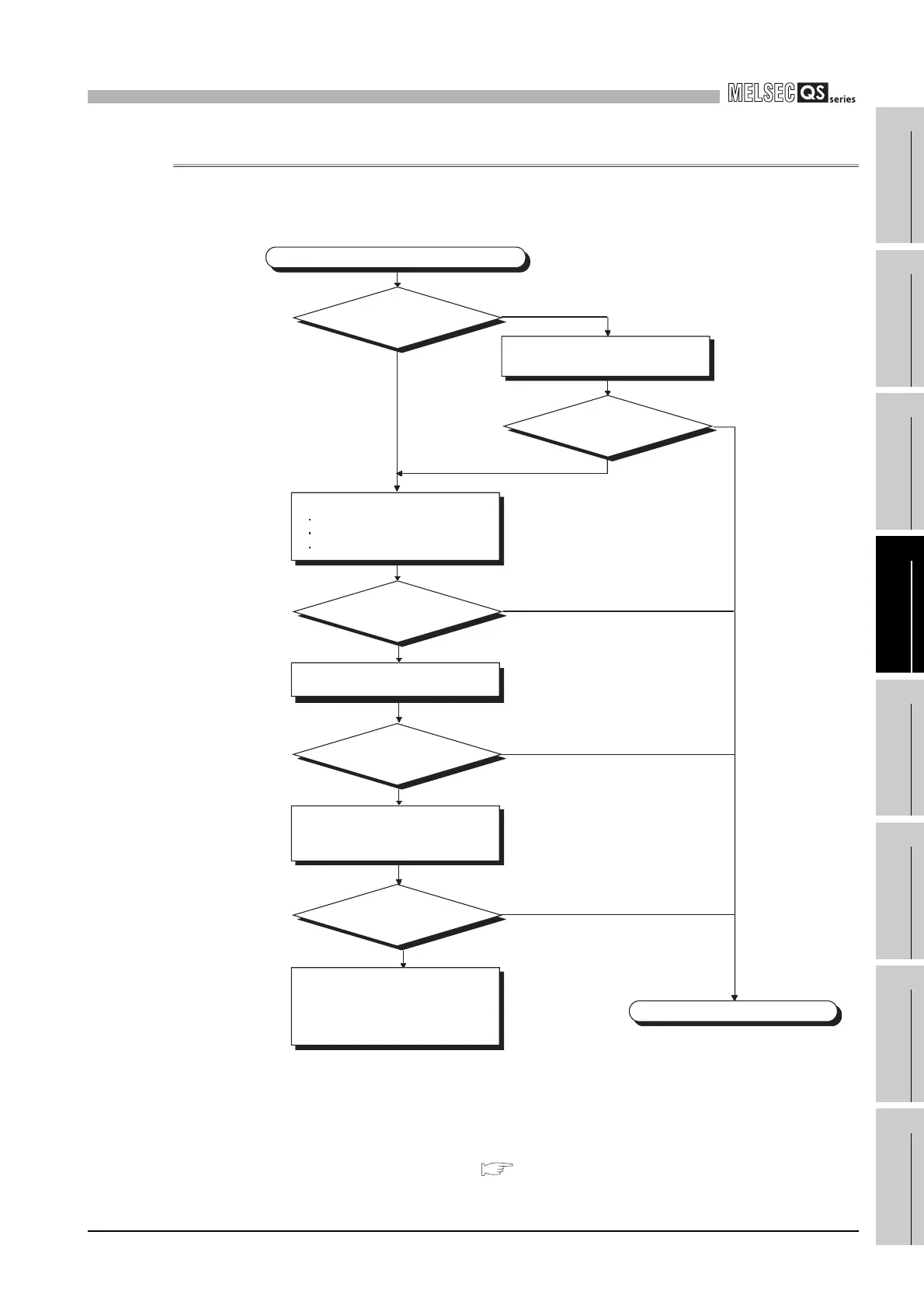
12.2.11 Flowchart for when a program cannot be written
The following shows the flowchart for when programs cannot be written in the CPU
module.
* 1: If the password registration cannot be canceled due to the loss of
password, initialize the PLC memory with GX developer.
The PLC memory initialization initializes the memory of the CPU
module (i.e. deletes all information in the CPU module) and resets
the memory to the factory default.
GX Developer Operating Manual (Safety PLC)
Figure 12.7 Flowchart for when a program cannot be written
NO
YES
NO
NO
YES
YES
YES
YES
A program cannot be written to the CPU
Completed
Can a program be
written?
Has the password
registered?
Format program memory.
Cancel the password using GX
Developer. *1
Perform the following.
Organize files.
Confirm memory space.
Confirm the writing destination.
Can a program be
written?
Can a program be
written?
Can the program be
written?
NO
Hardware error
Please consult your local Mitsubishi
service center of representative,
explaining a detailed description of
the problem.
NO
NO
Turn on power supply again and
initialize the PLC memory. Register
the CPU access password.

 Loading...

