9 - 4
9.1 Requirements for Conformance to EMC Directive
9.1.3 Cables
9
EMC AND LOW VOLTAGE DIRECTIVES
9.1.3 Cables
The cables pulled out from the control panel contain a high frequency noise component.
On the outside of the control panel, therefore, they serve as antennas to emit noise.
To prevent noise emission, use shielded cables when pulling out the cables which are
connected to CC-Link Safety master module, MELSECNET/H module, Ethernet module,
and CC-Link Safety remote I/O module and using them outside of the control panel.
The use of shielded cables also increases noise immunity.
For signal lines (including common line) of CC-Link Safety master module, MELSECNET/
H module, Ethernet module, and CC-Link Safety remote I/O module, the noise immunity
satisfies the standard value on the condition that the shielded cables are used for
grounding.
If shielded cables are not used or not grounded correctly, the noise immunity does not
meet the specified requirements.
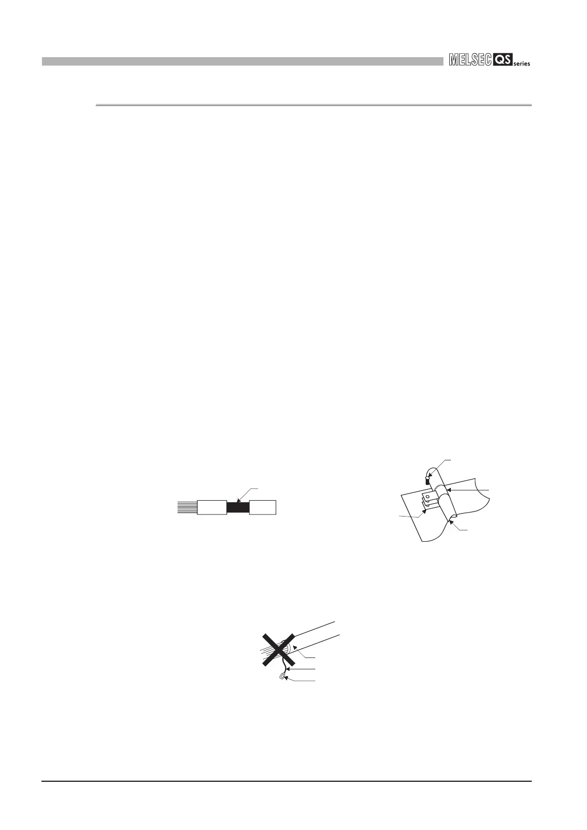
(1) Shield grounding processing of shielded cables
• Provide a grounding point on the shielded cable as near the module as possible
so that the wiring between the module and grounding point is not induced
electromagnetically by the other parts of wiring on the cable.
• Take appropriate measures so that the exposed shield part of the shielded cable,
where the cable jacket was partly removed, is grounded to the control panel on
the wildest contact surface.
A clamp may also be used as shown in Figure 9.2.
In this case, however, a mask painting is required for the inner wall of the control
panel which comes into contact with the clamp.
Note) If a wire is soldered onto the shield part of the shielded cable for grounding
as shown below, the high-frequency impedance rises, resulting in a loss of
shield effect.
Figure 9.1 Part to be exposed Figure 9.2 Shield grounding (Good example)
Figure 9.3 Shield grounding (Bad example)
Shield part
Screw
Clamp
Shield cable
Mask painting
Shield cable
Wire
Solderless terminal

 Loading...

