EasyManuals Logo

Mitsubishi MELSEC User Manual

Mitsubishi MELSEC
200 pages
To Next Page IconTo Next Page
To Previous Page IconTo Previous Page
Page #54 background imageLoading...
Page #54 background image
8 - 1
8.1 Procedure before Operating in SAFETY MODE
8
CPU MODULE START-UP PROCEDURES
CHAPTER8 CPU MODULE START-UP PROCEDURES
This chapter describes the procedure for starting up the CPU module.
It is assumed that programs and parameters have been created separately.
8.1 Procedure before Operating in SAFETY MODE
This section describes the procedure before operating the CPU module in SAFETY
MODE.
The default operation mode of the CPU module is TEST MODE. Switch the mode to
SAFETY MODE to operate the CPU module.
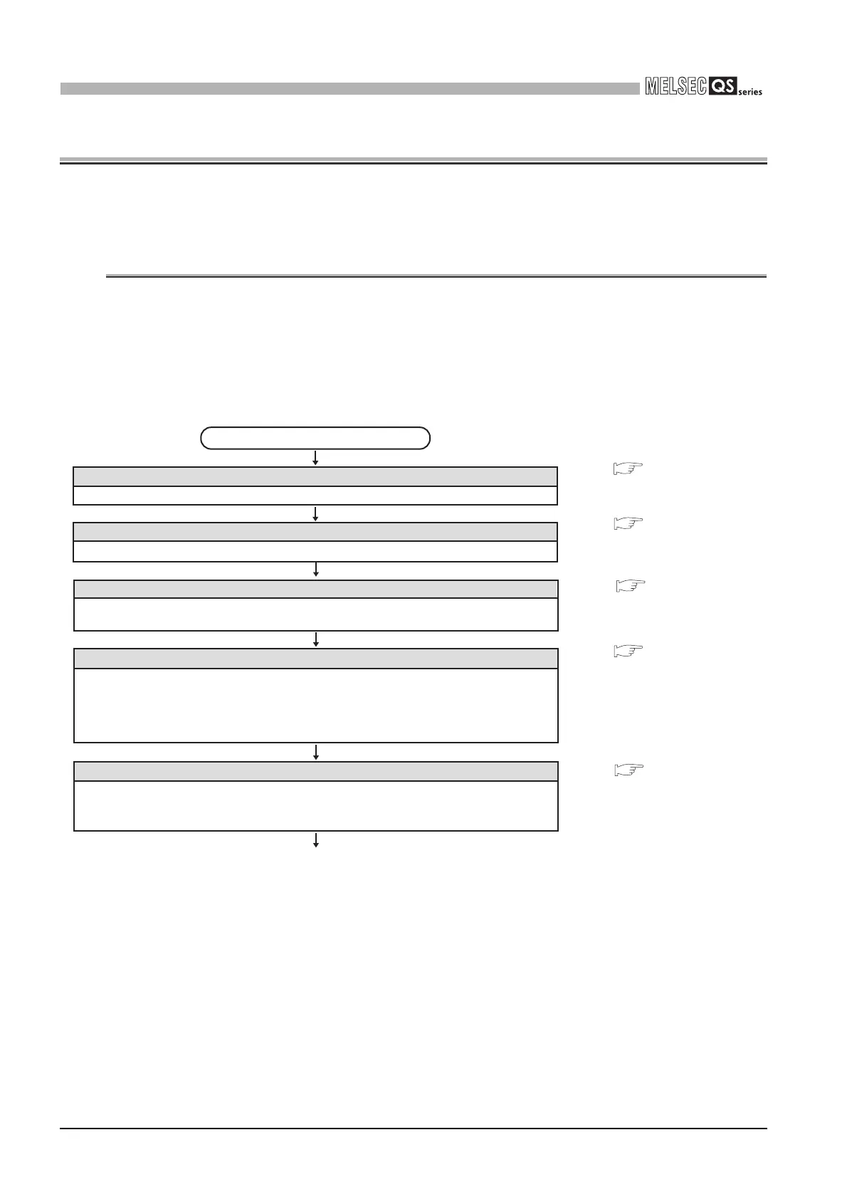
Installing a base unit
Install a base unit to a panel.
Installing modules
Install modules required for the system configuration to the base unit.
Fixing modules by screws
Fix the modules to the base unit with screws to prevent the displacement by vibrations or
other causes.
Wiring
1) Wire the power supply to the power supply module.
2) Install wiring between the CC-Link Safety master module and the CC-Link Safety remote
I/O module.
3) Wire external device(s) to the CC-Link Safety remote I/O module.
4) Install wiring between network modules.
(To the next page)
Start
1) Set the RUN/STOP/RESET switch of the CPU module to the STOP position.
(Set the CPU module to stop status.)
2) Make switch settings for the MELSECNET/H module.
Making initial settings of modules
• • • CHAPTER 10
• • • CHAPTER 2,
CHAPTER 10
• • • CHAPTER 10
• • • CHAPTER 4
MELSECNET/H Networ
System Reference Man
(PLC to PLC network)
• • • CHAPTER 10

Table of Contents

Questions and Answers:

Question and Answer IconNeed help?

Do you have a question about the Mitsubishi MELSEC and is the answer not in the manual?

Mitsubishi MELSEC Specifications

General IconGeneral
CategoryProgrammable Logic Controller (PLC)
ManufacturerMitsubishi Electric
SeriesMELSEC
Programming LanguagesLadder Diagram (LD), Function Block Diagram (FBD), Structured Text (ST), Instruction List (IL), Sequential Function Chart (SFC)
Communication ProtocolsEthernet, CC-Link, RS-232, RS-485, USB, Profibus, Modbus
Model SeriesFX, Q, L, iQ-R, iQ-F
Input Voltage100-240V AC, 24V DC (varies by model)
Memory CapacityVaries widely depending on the CPU module and series. Ranges from kilobytes to megabytes.
I/O Points16 to 8192 points (varies by model)
Communication PortsEthernet, RS-232, RS-485, USB (varies by model)
Programming SoftwareGX Works2, GX Works3, GX Developer
Operating Temperature0°C to 55°C
Storage Temperature-25°C to 75°C
Humidity5% to 95% (non-condensing)
Vibration Resistance10 to 57Hz, 0.075mm amplitude; 57 to 150Hz, 9.8m/s² acceleration
Shock Resistance147m/s², 3 times in each direction (X, Y, Z)
Protection ClassIP20 (varies by model)
CPU Processing Speed0.02μs to 0.1μs per instruction (varies by model)

Related product manuals