12
TROUBLESHOOTING
12.2 Troubleshooting Flowchart
12.2.4 When the "ALIVE" LED does not turn on or turns off
12 - 7
9
EMC AND LOW
VOLTAGE
DIRECTIVES
10
LOADING AND
INSTALLATION
11
MAINTENANCE AND
INSPECTION
12
TROUBLESHOOTING APPENDICES INDEX
12.2.4 When the "ALIVE" LED does not turn on or turns off
This section describes the troubleshooting for when the "ALIVE" LED of the CPU module
does not turn on at power-ON of the programmable controller or when the "ALIVE" LED
turns off during operation.
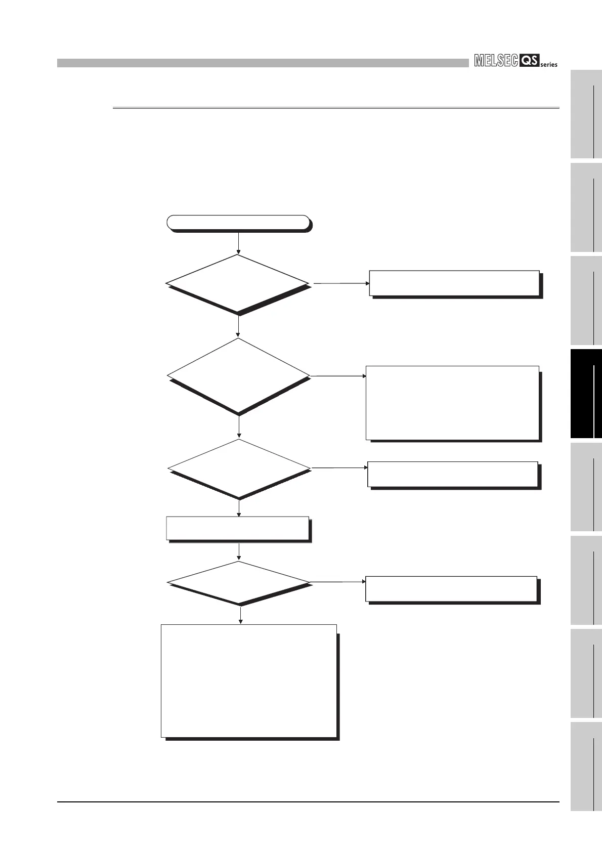
(1) Flowchart for when the "ALIVE" LED of the CPU module does not turn on at
power-ON of the programmable controller.
The "ALIVE" LED does not turn on.
Set the RUN/STOP/RESET switch to the
STOP position. If it is impossible to set it at
STOP position, failure of the CPU module is
suspected.
Please consult your local Mitsubishi service
center or representative, explaining a
detailed description of the problem.
RESET position
Possible
STOP/RUN position
Impossible
How is the "ALIVE" LED
of the CPU module?
How is the "POWER"
LED of the power supply
module?
Off
Off
On
On
Check the wiring and turn on all power
supplies.
Execute PLC diagnostics and
troubleshooting according to its result.
Hardware failure of the power supply module
before replacement is suspected.
Hardware failure of the following modules
1) CPU module
2) Base unit
3) CC-Link Safety master module
4) Network module (if mounted)
Execute operation check sequentially from
the minimum system.
For the module that does not operate, please
consult your local Mitsubishi service center or
representative, explaining a detailed
description of the problem.
Replace the power supply module and
check that the "POWER" LED is on.
Can the CPU module
communicate with GX
Developer?
Is RUN/STOP/RESET
switch of the CPU
module set at RESET
position?

 Loading...

