EasyManuals Logo

Mitsubishi MELSEC User Manual

Mitsubishi MELSEC
200 pages
To Next Page IconTo Next Page
To Previous Page IconTo Previous Page
Page #95 background imageLoading...
Page #95 background image
11
MAINTENANCE AND INSPECTION
11.3 Battery Life and Replacement Procedure
11 - 5
9
EMC AND LOW
VOLTAGE
DIRECTIVES
10
LOADING AND
INSTALLATION
11
MAINTENANCE AND
INSPECTION
12
TROUBLESHOOTING APPENDICES INDEX
11.3 Battery Life and Replacement Procedure
The battery installed in the CPU module is used for data retention during the power failure
of the program memory and error/operation history. Special relays SM51 and SM52 turn
on due to the decrease of battery voltage. Even if the special relays turn on, the program
and error/operation history data are not erased immediately.
After relay SM51 turns on, replace the battery quickly within the data retention time for
power failure (3 minutes).
POINT
SM51 turns on when the battery voltage falls below the specified value, and
remains ON even after the voltage is recovered to the normal value.
SM52 turns on when the battery voltage falls below the specified value, and turns
OFF when the voltage is recovered to the normal value.
After SM51 and/or SM52 turns on, replace the battery quickly.
SM51 and SM52 turn on when the battery voltage of the CPU module is lowered.
The battery voltage drop can be checked with the contents of the special registers SD51
and SD52.
For details of SD51 and SD52, refer to Section 12.7.
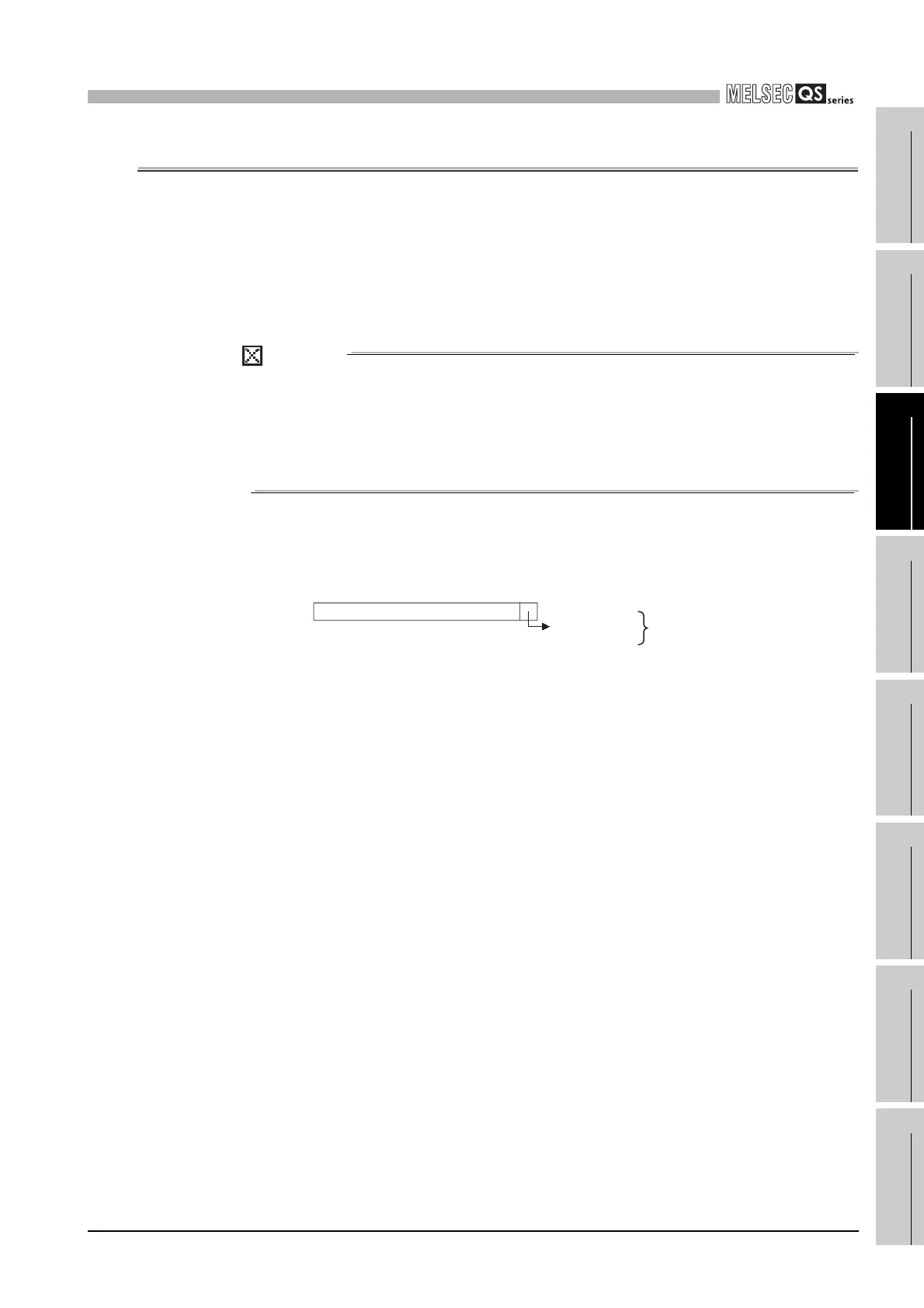
Figure 11.1 Bit pattern
When the battery
voltage is low, the
value is "1."
SD51, SD52
b15 b1 b0to
Fixed at 0
Error of a CPU
module battery

Table of Contents

Questions and Answers:

Question and Answer IconNeed help?

Do you have a question about the Mitsubishi MELSEC and is the answer not in the manual?

Mitsubishi MELSEC Specifications

General IconGeneral
CategoryProgrammable Logic Controller (PLC)
ManufacturerMitsubishi Electric
SeriesMELSEC
Programming LanguagesLadder Diagram (LD), Function Block Diagram (FBD), Structured Text (ST), Instruction List (IL), Sequential Function Chart (SFC)
Communication ProtocolsEthernet, CC-Link, RS-232, RS-485, USB, Profibus, Modbus
Model SeriesFX, Q, L, iQ-R, iQ-F
Input Voltage100-240V AC, 24V DC (varies by model)
Memory CapacityVaries widely depending on the CPU module and series. Ranges from kilobytes to megabytes.
I/O Points16 to 8192 points (varies by model)
Communication PortsEthernet, RS-232, RS-485, USB (varies by model)
Programming SoftwareGX Works2, GX Works3, GX Developer
Operating Temperature0°C to 55°C
Storage Temperature-25°C to 75°C
Humidity5% to 95% (non-condensing)
Vibration Resistance10 to 57Hz, 0.075mm amplitude; 57 to 150Hz, 9.8m/s² acceleration
Shock Resistance147m/s², 3 times in each direction (X, Y, Z)
Protection ClassIP20 (varies by model)
CPU Processing Speed0.02μs to 0.1μs per instruction (varies by model)

Related product manuals