12
TROUBLESHOOTING
12.2 Troubleshooting Flowchart
12.2.3 Flowchart for when the "POWER" LED turns off
12 - 5
9
EMC AND LOW
VOLTAGE
DIRECTIVES
10
LOADING AND
INSTALLATION
11
MAINTENANCE AND
INSPECTION
12
TROUBLESHOOTING APPENDICES INDEX
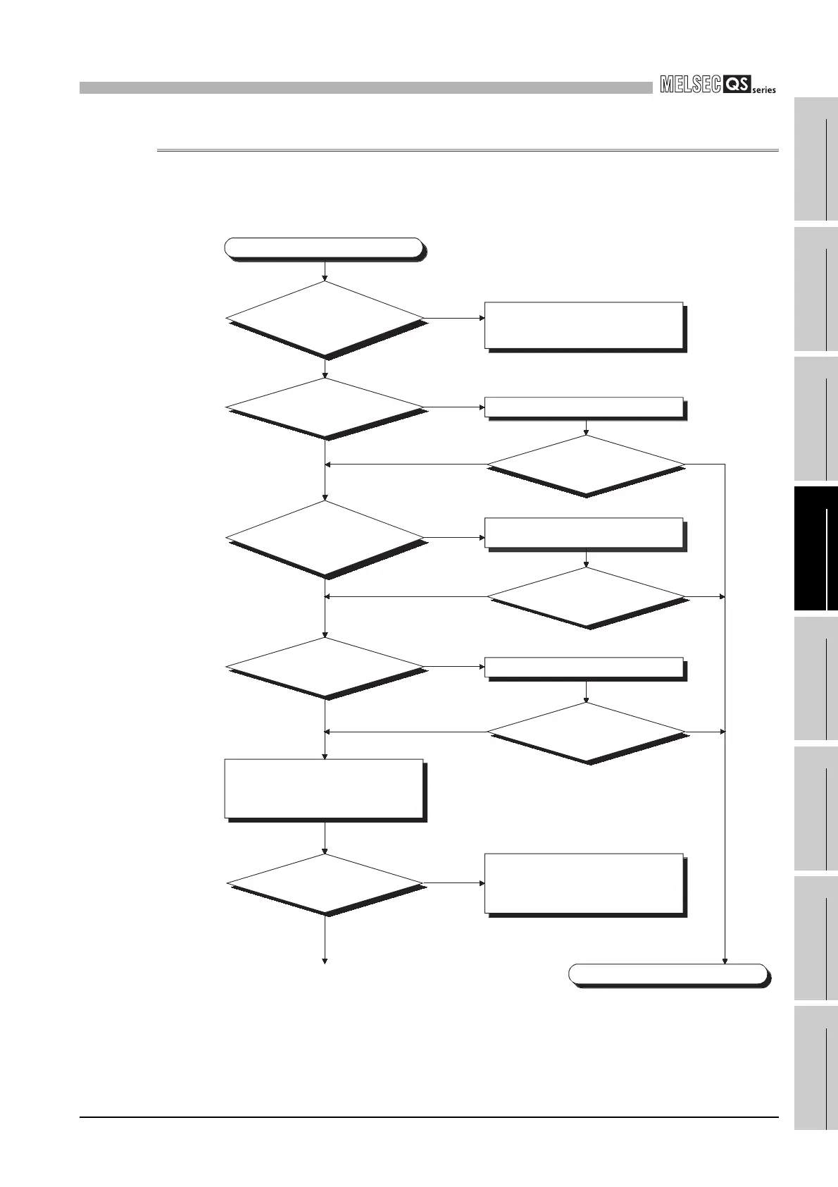
12.2.3 Flowchart for when the "POWER" LED turns off
The following shows the flowchart for when the "POWER" LED of the power supply
module turns off at of the programmable controller power-on or during operation.
(To next page)
The "POWER" LED has turned off.
Is there a
power supply?
Is the power
supply module fixed?
Completed
Properly fix the power supply module.
The base unit that includes the
corresponding power supply module
is faulty.
How is the "POWER" LED?
How is the "POWER" LED?
Remove all modules other than
the power supply module from
the base unit.
YES
YES
YES
NO
NO
NO
Off
Off
Off
Off
On
On
On
On
Supply power.
Off
The "POWER" LED of the power
supply module is faulty. (Replace it
by a normal power supply module.)
On
How is the "POWER" LED?
The supply voltage should be within
the rated range.
How is the "POWER" LED?
Is the power
supply voltage within
the voltage range given in the
specifications?
Has the
"ALIVE" LED of the
CPU module turned on?

 Loading...

