12 - 14
12.2 Troubleshooting Flowchart
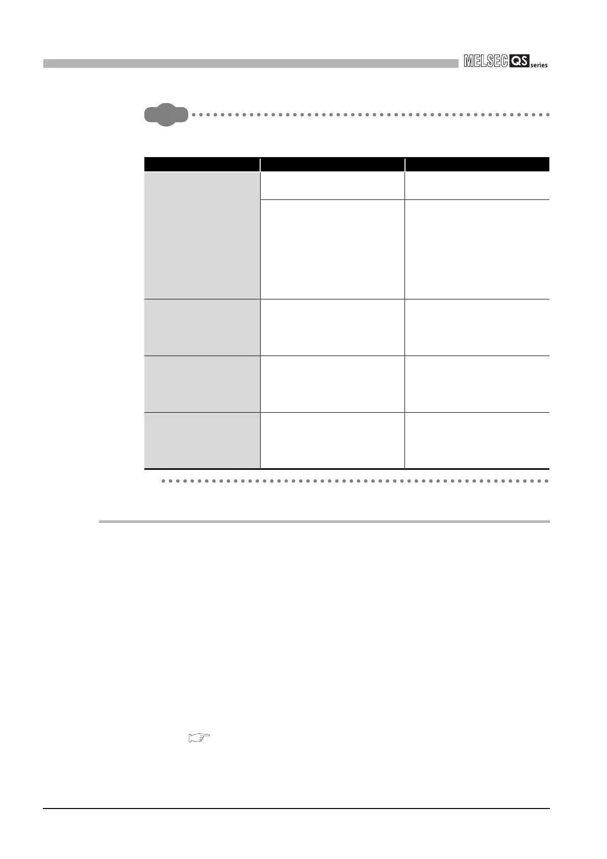
12.2.8 When the "USER" LED turns on
12
TROUBLESHOOTING
Remark
The following causes are possible when the "ERR." LED of the CPU module
flashes at PLC power-on.
12.2.8 When the "USER" LED turns on
If the "USER" LED turns on, follow the steps described below.
The "USER" LED turns on when an error is detected by the annunciator (F) turns on.
If the "USER" LED turns on, monitor the special relay SM62 and the special registers
SD62 to SD79 in the monitor mode of GX Developer.
• When M62 has turned ON
The annunciator (F) is ON.
Using SD62 to SD79, check the error cause.
Eliminate the error cause after confirming it.
The "USER" LED can be turned off by:
• Making a reset with the RUN/STOP/RESET switch.
• Canceling Errors with the special relay and the special register
( Section 12.4)
Error Message Cause Corrective Action
MODULE LAYOUT
ERROR
(Error code: 2125)
The multiple CPU system is
configured.
Remove all CPUs except the
safety CPU from the base unit.
Modules except the following are
mounted on the base unit.
• CC-Link Safety master module
• CC-Link IE controller network
module
• MELSECNET/H module
• Ethernet module
Remove all modules other than
described on the left.
CC-LINK PARAMETER
ERROR
(Error code: 3105)
The CC-Link Safety master
module is mounted with
configuration not for a master
station.
Set the CC-Link Safety master
module to the master station.
NETWORK PARAMETER
ERROR
(Error code: 3100)
The MELSECNET/H module is
mounted with configuration not for
a PLC to PLC network normal
station.
Set the MELSECNET/H module
to a PLC to PLC network normal
station.
NETWORK PARAMETER
ERROR
(Error code: 3103)
The number of Ethernet modules
actually mounted is different from
that is set in Network parameter
for Ethernet.
Correct either the setting or
mounting status so that they
become the same.

 Loading...

