12 - 2
12.2 Troubleshooting Flowchart
12.2.1 Troubleshooting category flow
12
TROUBLESHOOTING
12.2 Troubleshooting Flowchart
The trouble investigating methods and remedies of the troubles are described below.
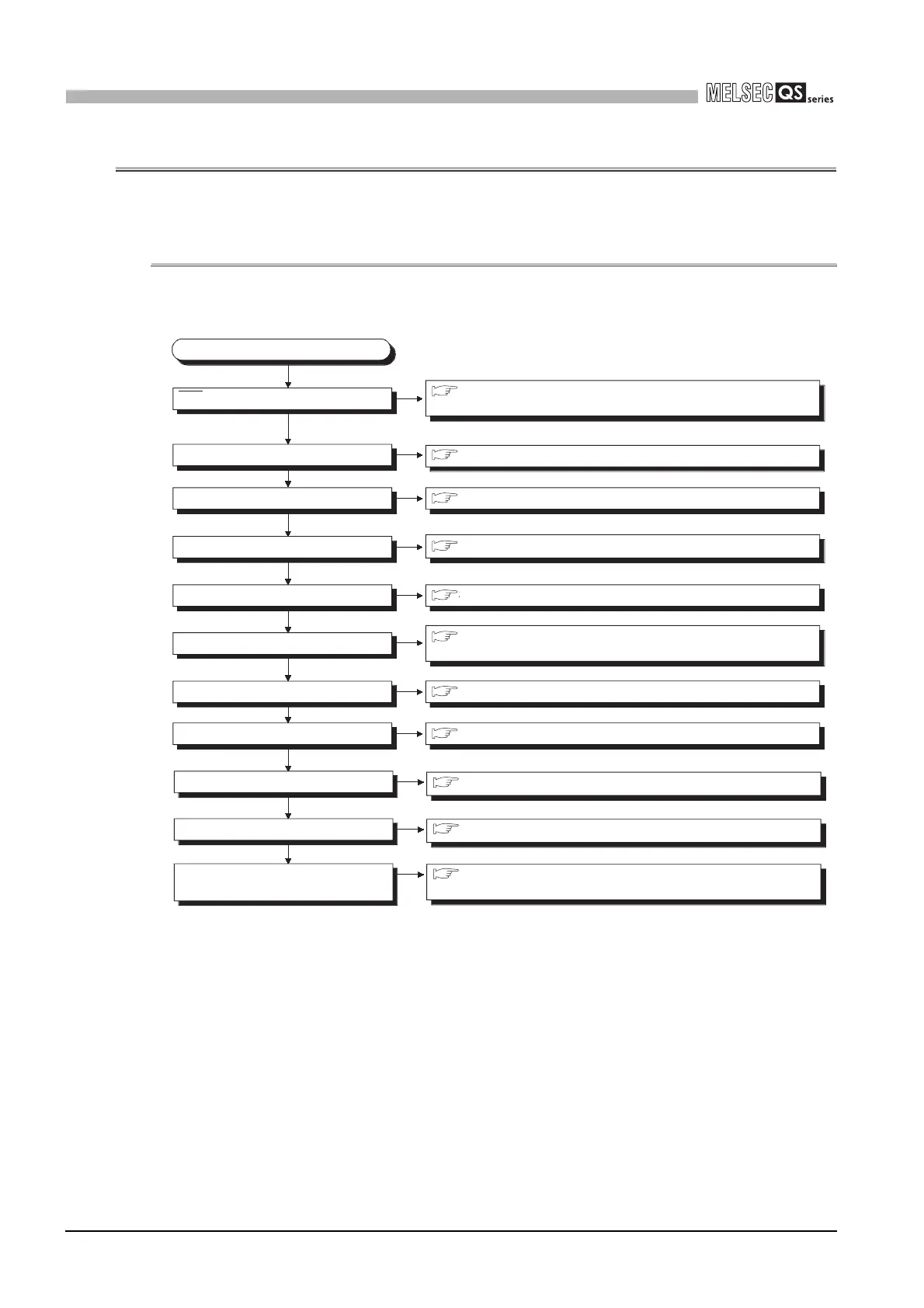
12.2.1 Troubleshooting category flow
This section classifies the error by definition and describes them.
Figure 12.1 Troubleshooting flowchart
The CPU cannot communicate
with the GX Developer
Flowchart for when the CPU cannot
communicate with the GX Developer
Error-occurrence description
"POWER" LED off
"RUN" LED off
"RUN" LED flashing
Section 12.2.8 When the "RUN" LED is flashing
"ALIVE" LED off
When the "ALIVE" LED does not come on or is off
"ERR." LED on/flashing
ERR terminal turned off (opened).
When the "USER" LED is on
"USER" LED on
When the "BAT. " LED is on
"BAT. " LED on
Flowchart for when the "POWER" LED turns off
Flowchart for when the ERR terminal
(negative logic) is off (opened)
Flowchart for when the "RUN" LED turns off
Flowchart for when the "ERR." LED turns on or
flashes
Unable to read a program
Unable to write a program
Flowchart for when a program cannot be read
Flowchart for when a program cannot be written
Section 12.2.5
Section 12.2.3
Section 12.2.4
Section 12.2.7
Section 12.2.8
Section 12.2.9
Section 12.2.10
Section 12.2.11
Section 12.2.6
Section 12.2.2
Section 12.2.12

 Loading...

