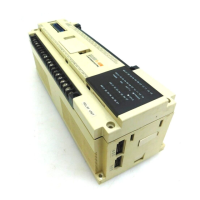
Do you have a question about the Mitsubishi MELSEC F2-60MR and is the answer not in the manual?
| Brand | Mitsubishi |
|---|---|
| Model | MELSEC F2-60MR |
| Category | Controller |
| Language | English |
Specifies power supply voltage, consumption, and DC24V output capacity for the F2 series.
Provides guidelines for proper grounding of the base and extension units for safety and noise reduction.
Explains the connection and function of RUN/STOP mode terminals for controlling the PC operation.
Provides specifications for DC24V, AC100V, and AC200V input circuits, including voltage, current, and response time.
Details the wiring and common terminals for F2-40/60MR and F2-40/60ER relay output models.
Explains the wiring and specifications for F2-40/60MS and F2-40/60ES Triac (SSR) output models.
Covers wiring and load limitations for F2-40/60MT and F2-40/60ET sink output transistor models.
Summarizes output circuit specifications for Relay, Triac, and Transistor outputs, including load, current, and response time.
Lists essential checks to perform before operating the unit, covering connections, settings, and programs.
Explains how to interpret base unit LED indicators for power, run, battery, and program errors.
Covers periodical checks, battery replacement frequency, and environmental considerations for PC maintenance.


 Loading...