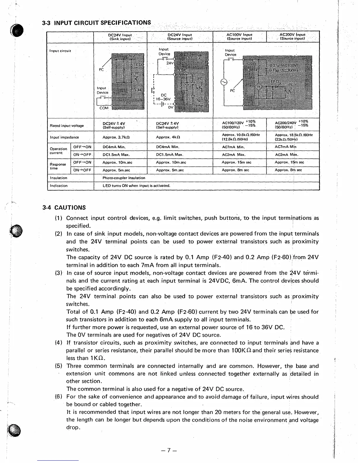
3-3
INPUT CIRCUIT SPECIFICATIONS
Operation
current
__ ~
1
OC24V Input DC24V Input
(Sink input)
DC4mA Min.
OFF-'ON DC4mA Min.
I
I
Response
time
lnpuf
Input circuit
OFF-'ON Approx.
l0m.sec
Approx. 10m.sec
ON-+OFF
Approx. 5m.sec Approx. 5rnsec
DC24V
=k
4V
DC24V 5 4V
(Self-supply) (Self-supply)
Rated input voltage
I
I
I I
I
Insulation Photocoupler insulation
lnout
AC2mA Max. AC2mA Max.
Approx. 15m sec
Approx.
8m
sec
Approx.
t5m
sec
Approx.
8m
sec
I
Indication
1
LED turns ON when input
is
activated.
3-4
CAUTlONS
(I)
Connect input control devices,
e.g.
limit switches, push butto&, to the input terminations
as
specified.
(2) In case of sink input models, non-voltage contact devices are powered from the input terminals
and the 24V terminal points can be used to power external transistors such
as
proximity
switches.
The
capacity of 24V
DC
source
is
rated by
0.1
Amp
(F2-40)
and 0.2 Amp
(FZ-60)
from 24V
terminal in addition to each 7mA from
all
input terminals.
(3)
In case of source input modefs, non-voltage contact devices are powered from the 24V termi-
nals and the current rating
at
each input terminal
is
24VDC, 6mA. The control devices should
be specified accordingly.
The 24V terminal points can also be used to power externaf transistors such
as
proximity
switches.
Totaf
of
0.1
Amp (F2-40) and 0.2 Amp
(F2-60)
current by two 24V terminals can be used for
such transistors in addition to each
6mA
suppty to
all
input terminals.
If further more power
is
requested, use an externaf power source of
16
to
36V DC.
The
OV
terminals
are
used for negatives of 24V
DC
source.
(4)
If
transistor circuits, such
as
proximity switches, are connected to input terminals and have
a
parallel or series resistance, their parallel should be more than
10OKL-l
and their series resistance
less
than
1
KO2.
(5)
Three common terminals
are
connected internally and are common. However, thte base and
extension unit commons are not linked unless connected together externalfy
as
detailed in
other section.
The common terminal
is
also used for
a
negative
of
24V
DC
source.
(6)
For the sake of convenience and appearance and to avoid damage of failure, input wires should
be bound or cabled together.
It:
is
recommended
that
input wires are not longer than 20 meters for the general use, However,
the tength can be longer but depends upon the conditions of the noise environment and voltage
drop.
-7-

 Loading...


