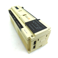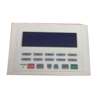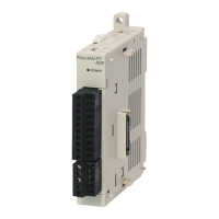
Do you have a question about the Mitsubishi MELSEC F2-40MR and is the answer not in the manual?
| Manufacturer | Mitsubishi Electric |
|---|---|
| Series | MELSEC F |
| Model | F2-40MR |
| Input Points | 24 |
| Output Points | 16 |
| Output Type | Relay |
| Input Voltage | 100-240VAC |
| Input Frequency | 50/60 Hz |
| Operating Temperature | 0 to 55 °C |
| Storage Temperature | -25 to 70 °C |
| Weight | 0.8 kg |
| Type | Programmable Logic Controller (PLC) |
| Humidity | 5 to 95%RH (non-condensing) |
Details power supply voltage requirements, consumption, and DC 24V output capacity for different F2 series models.
Explains the connection and function of RUN/STOP mode terminals for system control and emergency stops.
Details the use of DC24V terminals for powering input devices and connecting between base and extension units.
Illustrates wiring examples for sink and source input models, showing connections for switches and sensors.
Shows wiring diagrams and common terminal arrangements for F2-40/60MR and F2-40/60ER relay output models.
Details wiring and specifications for F2-40/60MS and F2-40/60ES Triac (SSR) output models.
Illustrates wiring for F2-40/60T Sink and F2-40/60ET Source transistor output models.
Explains how to check the power supply status using the unit's LED indicator.
Details how to diagnose the unit's run status via the RUN indicator LED.
Identifies causes for program errors indicated by the CPU ERROR LED flicker.
Explains CPU execution errors, ROM handling, and watchdog timer errors indicated by the CPU ERROR LED.
Discusses troubleshooting input LED failures, including issues with input device rating and leakage current.
Covers troubleshooting output failures, such as issues with low current devices or short circuits.


 Loading...