11
Connect external load devices e.g. contactors, pilot lamps, solenoid (electromagnetic)
to output terminations of the base unit and extension unit (if used).
The
load
limitation
of
the transistor outputs
is
1A
for
each individual output, but
output load should not exceed
2A
per
4
points
at
DC
24V.
Due to surge current limitations lamp loads should be within
3W.
When other load are connected
to
a
output termination in addition to lamp load, the total collec-
tive
output load should be
as
specified with reference to following table.
2w
6W
1w
16W
0
24W
i
The
external
DC
power supply
should
be
DC
24V
+I
5%/-30%.
2A rated back-up fuses or protectors are recommended per each four outputs to prevent damage
to the circuit boards of the
PC
in the event
of
a
short circuit fault in one
of
the external ,circuits.
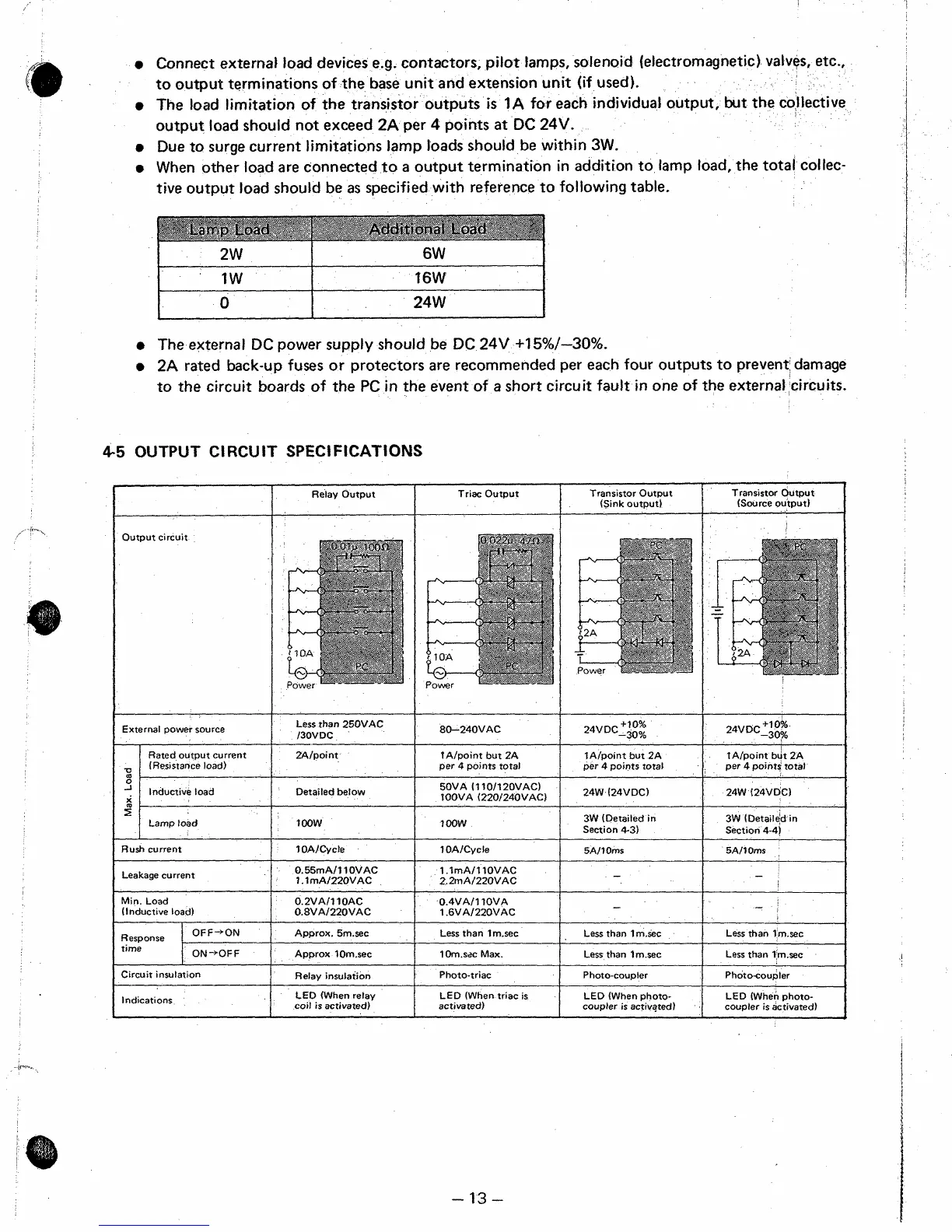
4-5
OUTPUT CIRCUIT SPECIFICATIONS
Relay Output
Triac Output
Transistor Output
(Source output)
Transistor Output
(Sink output)
~~
Output circuit
+?O%
24vDc-30%
Less
than 250VAC
I30VDC
2AIpoint
Detailed below
+lo%
24VDC-30F
tA/point but 2A
per
4
points total
24W (24VDC)
3W (Detailed in
Section 4-4)
SA11
Oms
External power source
Rated output current
(Resistance load)
Lamp load
Rush
current
Leakage current
Min. Load
(Inductive load)
80-240VAC
tA1point but 2A
per
4
points toral
50VA
(1
loll
20VAC)
1
OOVA (220/240VAC)
IA/point but 2A
per
4
points total
24W (24VDC)
3W (Detailed in
Section
4-3)
tOOW
lOOW
1 OAICycle
1 .lmAIllOVAC
2.2mA1220VAC
1OAICycle
0.55mA111 OVAC
l.lmAl220VAC
BAllOms
-
0.2VAlllOAC
0.8VAl220VAC
0.4VAIl TOVA
1.6VAl220VAC
-
I
Less than Irn.sec
Less than 1m.sec
Phot ocoupler
Approx. 5m.sec
Less than 1m.sec
Response
time
Circuit insulation
Indications
Less than 1m.sec
Approx l0m.sec
1Om.szc Max.
Less than 1 msec
!
Relay
insulation
Photo-triac
Photo-coupler
LED (When triac is
activated)
LED (When photo-
coupler is activated)
LED (When photo-
coupler is activated)
LED
(When relay
coil
is
activated)
-13-
 Loading...


