,
,
I
INARY
CHECKS
8-2
ope
the unit,
it
is
advisable to carry out
the following checks:
a.
That the power and ground leads are properly con-
nected.
b. That input and output leads
are
property connected
and not entangled.
(It
is
worthwhile numbering each
load according to
is
input and output assignment.)
c.
that output loads and input contacts are within the
specification
I
imits detailed earlier.
d. That program/monitor mode on the programming
panel and RUN/STOP mode on the base unit are
properly
set.
e.
That the extension cable
is
properly connected.
f.
Programmes can be checked and monitored by using
the facility available on the programming panet for
this purpose.
r
i
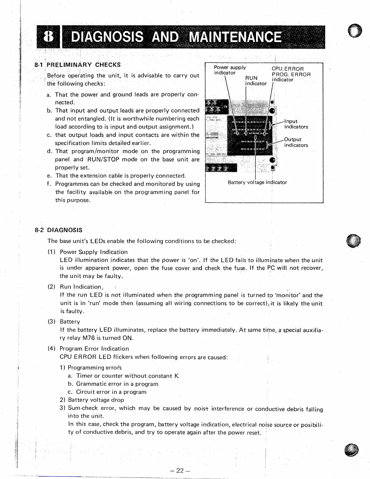
Power
supply
CPU.
ERROR
I
PROG. ERROR
jndi$Or
RUN
indicator
indicator
I
Battery vot
tage indicator
DIAGNOSIS
The base unit's
LEDs
enable the following conditions to be checked:
(1
1
Power Supply
t
ndication
LED
illumination indicates that the power
is
'on'. If the
LED
fails to illuminate when the unit
is
under apparent power, open the fuse cover and check the fuse. If the
PC
will
not recover,
the unit may be faulty.
ff the run
LED
is
not illuminated when the programming panel
is
turned to 'monitor' and the
unit
is
in 'run' mode then (assuming
all
wiring connections
to
be correct),
it
is
likely the unit
is
faulty.
tf the battery
LED
iltuminates, replace the battery immediately. At same time,
a
special auxitia-
ry relay
M76
is
turned
ON.
(2)
Run indication,
.
(3)
Battery
(4)
Program Error tndication
CPU
ERROR
LED
flickers when following errors are caused:
I
)
Programming errofs
a.
Timer or counter without constant
K
b. Grammatic error in
a
program
c,
Circuit error in
a
program
2)
Battery voltage drop
3}
Sum-check error, which may be caused by nois? interference or conductive debris falling
into the unit.
In this
case,
check the program, battery voltage indication, electrical noise source or posibili-
ty of conductive debris, and try to operate again
after
the power reset.
'
22
-
I
I
 Loading...


