I/
,
I
Connect external load devices e.g. contactors, pilot lamps, sotenoid (electromagnetic)
valves,
etc.,
to output terminations of the base unit and extension unit (if used).
As
shown in the above figure, common terminals are provided
for
the output terminations.
As these commons are not linked and cover each four output terminals in their block, different
types of power can be used
as
shown in the above example
as
far
as
the output terminals in
a
block share one type
of
power.
The load limitation of the triac
(SSR)
outputs
is
1A
for each individual output, but the total
collective output load should no exceed
8A
across
all
16
outputs
at
AC
110/120V or
AC
220/
24OV.
For inductance loads, the rated coil of magnetic contactors
sl-tould
be within 50VA
at
AC
110/
be required. For lamp loads above
IOOW,
an external relay will atso be required.
Each triac
(SSR)
inside the
unit
will withstand moderate surge currents, and
is
protqcted bv
a
residual current circuit. With the triac
'off'
current leakage
is
less
than 1.2mA
at
AC 120V or
2.2mA
at
AC
220V. However,
it
is
possible that this might have some effect on external loads.
It
is
not possible to operate triac output card
on
DC
toads.
I
12OV
or 100VA
at
AC 220/240V. If the coil toad
is
over these limits, then an externa1)relay
will
i
?
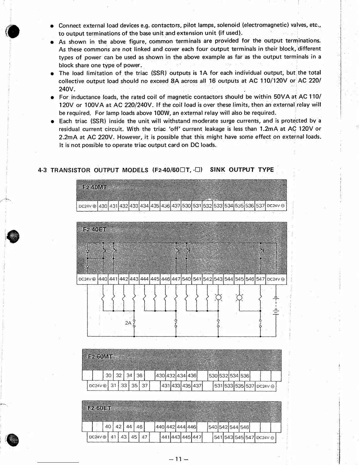
4-3
TRANSfSTOR
OUTPUT
MODELS
(F2-40/60CIT,
-17)
SINK
OUTPUT
TYPE
1
DC24V
0
14301 431
/4321433143414351436f437[53015311532[5331534i
535[536[5371
DC24V
0
I
d
2A
t
P
b
4
DC24VO 31 33 35 37 431 433 435 437 531 533 535 537 DC24VO
40 42 44 46 440 442 444 446 540 542 544 546
DC24VO
41
43 45 47 441 443 445 447
541
543 545 547
DC24V
@
 Loading...


