12
TROUBLESHOOTING
12.2 Troubleshooting Flowchart
12.2.5 Flowchart for when the "RUN" LED turns off
12 - 9
9
EMC AND LOW
VOLTAGE
DIRECTIVES
10
LOADING AND
INSTALLATION
11
MAINTENANCE AND
INSPECTION
12
TROUBLESHOOTING APPENDICES INDEX
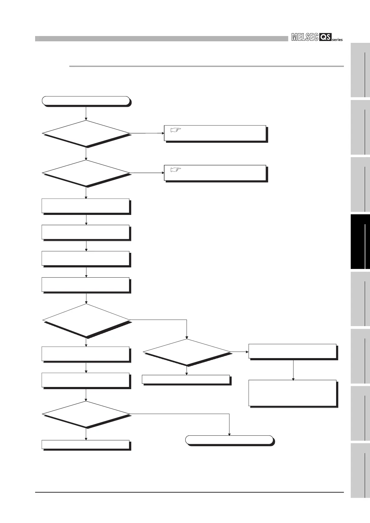
12.2.5 Flowchart for when the "RUN" LED turns off
The following shows the flowchart for when the "RUN" LED of
the CPU module turns off during operation of the PLC.
Figure 12.4 Flowchart for when the "RUN" LED turns off
YES
NO
The "RUN" LED has turned off.
Completed
Does the "RUN" LED
turn on?
How
is the "POWER"
LED of the power supply
module?
Is the "ERR." LED
on/flashing?
Off
On
Section 12.2.3 Flowchart for when
the "POWER" LED turns off
Section 12.2.7 Flowchart for when
the "ERR." LED is on/flashing
YES
YES
NO
Reset the CPU module
RUN/STOP/RESET switch.
Set the CPU module
RUN/STOP/RESET switch to STOP.
Write END to sequence step 0 with
GX Developer.
Set the CPU module
RUN/STOP/RESET switch to RUN.
Is the
operation monitored
by GX Developer
possible?
Possible cause is a sequence
program error.
Check the program and modify
the program error location.
Has
measures been
taken against noise?
Take measures against noise.
Possible cause is a PLC part
fault/poor connection.
Please consult your local Mitsubishi
service center of representative,
explaining a detailed description of
the problem.
NO
YES
NO
Replace the CPU module.
Section 12.2.7
Section 12.2.3

 Loading...

