3.
SPECIFICATIONS
/MELSEC-A
3.6
I/O
Signals
To
and
From
PC
CPU
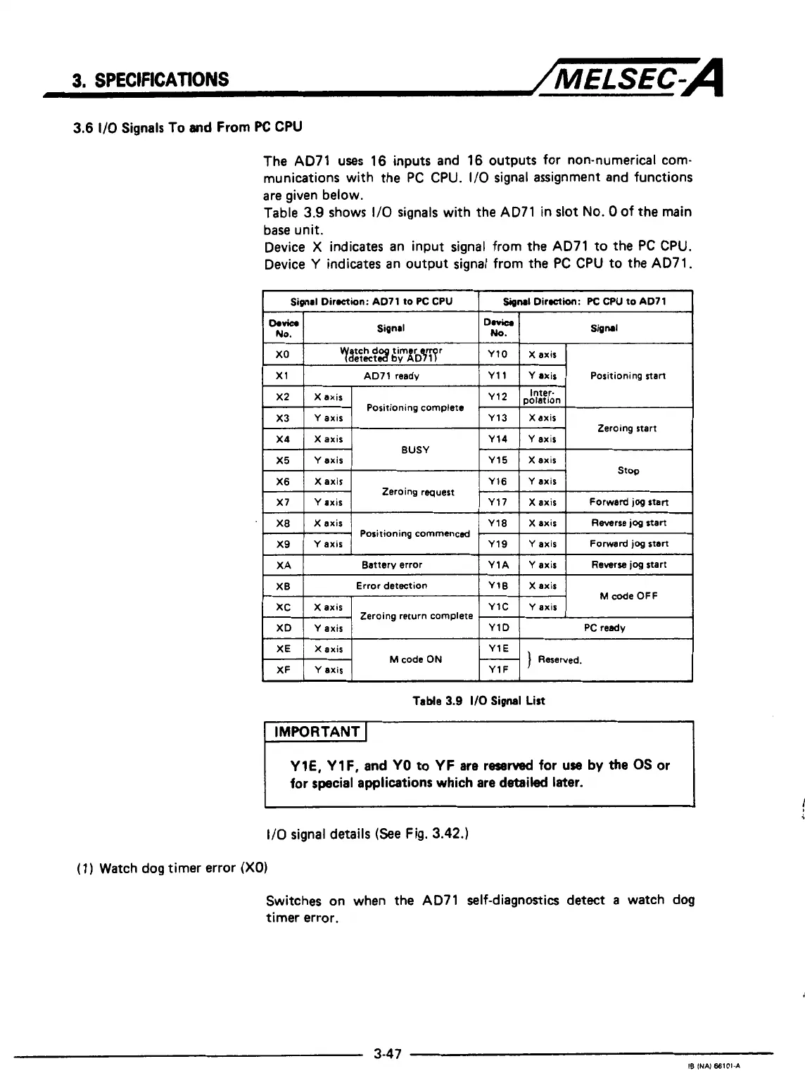
The AD71 uses 16 inputs and 16 outputs for non-numerical com-
munications with the
PC
CPU.
1/0
signal assignment and functions
are given below.
Table 3.9 shows
1/0
signals with the AD71 in slot
No.
0
of the main
base unit.
Device
X
indicates an input signal from the AD71 to the
PC
CPU.
Device
Y
indicates an output signal from the
PC
CPU to the AD71.
I
Signal
Dirwion: AD71
to
PC CPU
Signal
Direion:
PC
CPU
to AD71
I
DOViCbl
No.
Sinal
Signal
x1
Y axis Positioning stan Y11
AD71 ready
X2
Positioning complete
Y axis
X3
p$;;[on
Y 12
X axis
Y13 Xaxis
Zeroing start
X4
Zeroing request
Y axis
Y16 X axis
X6
Xaxis Y15 Y axis
X5
BUSY
Y axis
Y14
X axis
X?
Y
axis
Y 17 X axis
Forward
jog
start
X8
X axis
Y18
Forward
jog
start
Y axis
Y19
Y
axis
X9
Reverse
jog
start
Xaxis
stop
Positioning commenced
.
XA
PC ready
Y1D Y axis
XD
Y axis
Y1C Xaxis
XC
Xaxis
Y1B Error detection
XB
Reverse
jog
start
Y
axis Y1A
Battery error
M
code
OFF
Zeroing return complete
r
XE
Y1F
Y axis
XF
Y1E
Xaxis
M
code
ON
)
Reserved.
i
Table
3.9
I/O
Signal
List
IMPORTANT
I
YlE, Y lF,
and
YO
to
YF
are
reserved for use
by
the
OS
or
for special applications which are detailed
later.
~~
I/O
signal details
(See
Fig.
3.42.)
(1)
Watch
dog
timer error
(XO)
Switches on when the AD71 self-diagnostics detect
a
watch dog
timer error.
*
I
r
3-47
?
IB
INN
68101-A

 Loading...


