ABS <4WD> -
Troubleshooting
35B-24
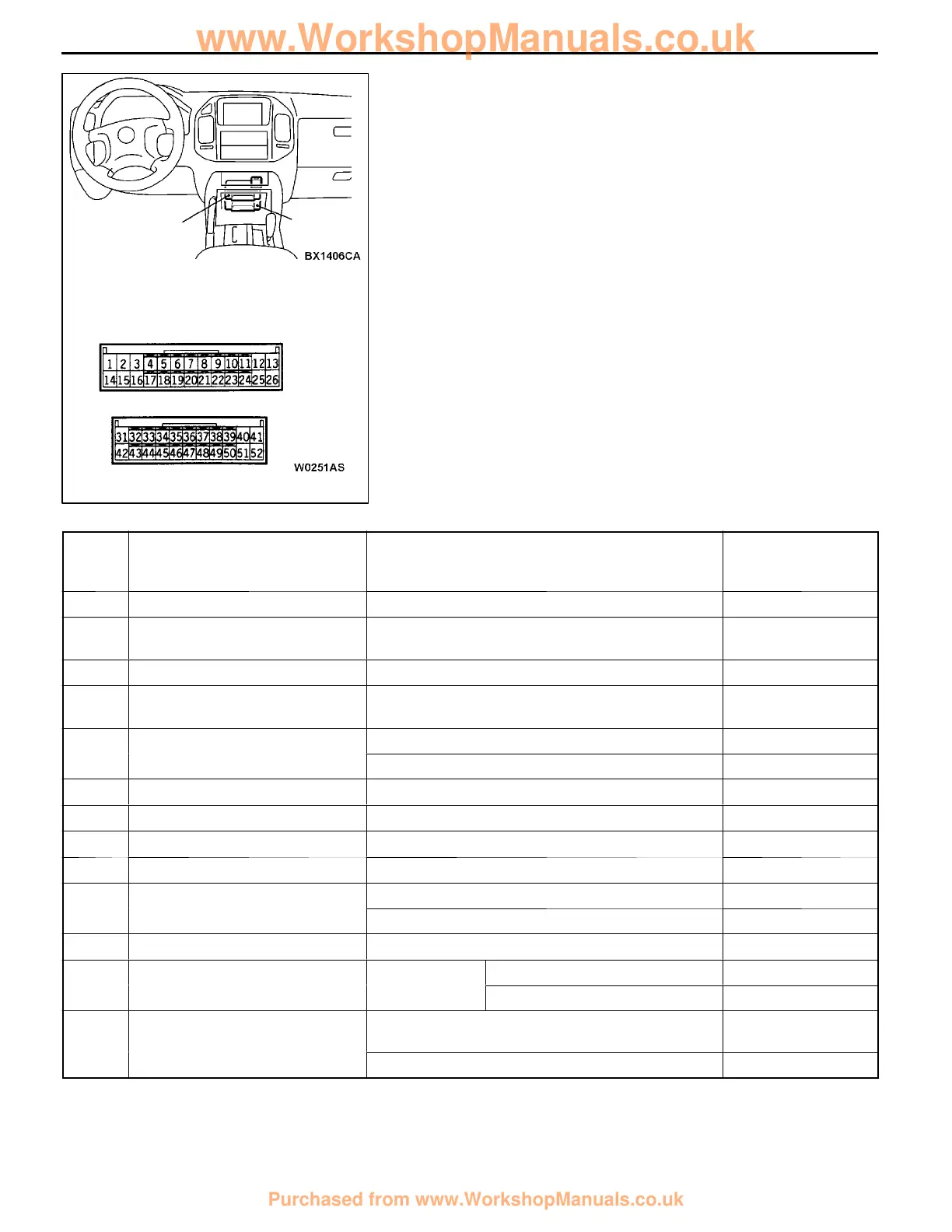
CHECK AT ABS-ECU TERMINAL
TERMINAL VOLTAGE TABLE
NOTE
There are two ECUs with the same shape inside the floor
console, o n e above the other. The upper ECU is the ABS-ECU
and has a blue connector. The lower ECU is the transfer-ECU
and has a green connector.
(1) Measure the voltages between the respective terminal
and earth.
(2) The terminal layout is shown in the illustration.
Termi-
nal
No.
Check item Inspection conditions Normal condition
1 Control solenoid valve OUT (FL) Ignition switch: ON System voltage
2 Control solenoid valve OUT
(RR)
Ignition switch: ON System voltage
3 Select solenoid valve (FL) Ignition switch: ON System voltage
4 G sensor input Ignition switch: ON
Vehicle horizontal position
2.4 - 2.6 V
13 ABS-ECU power supply
Ignition switch: ON System voltage
Ignition switch: START 0V
14 Control solenoid valve IN (FL) Ignition switch: ON System voltage
15 Control solenoid valve IN (RR) Ignition switch: ON System voltage
16 Select solenoid valve (FR) Ignition switch: ON System voltage
18 G sensor earth At all times 0.5 V or less
31 ABS-ECU power supply
Ignition switch: ON System voltage
Ignition switch: START 0V
33 Rear differential lock switch Ignition switch: ON System voltage
34 Stop lamp switch input Ignition
Stop lamp switch: ON System voltage
switch: ON
Stop lamp switch: OFF 2 V or less
36 MUT-II
When the MUT- II is connected Serial communica-
tion with the MUT-II
When the MUT- II is not connected 1 V or less
ABS-
ECU
ABS-ECU side connector
Transfer-ECU
www.WorkshopManuals.co.uk
Purchased from www.WorkshopManuals.co.uk
 Loading...