56
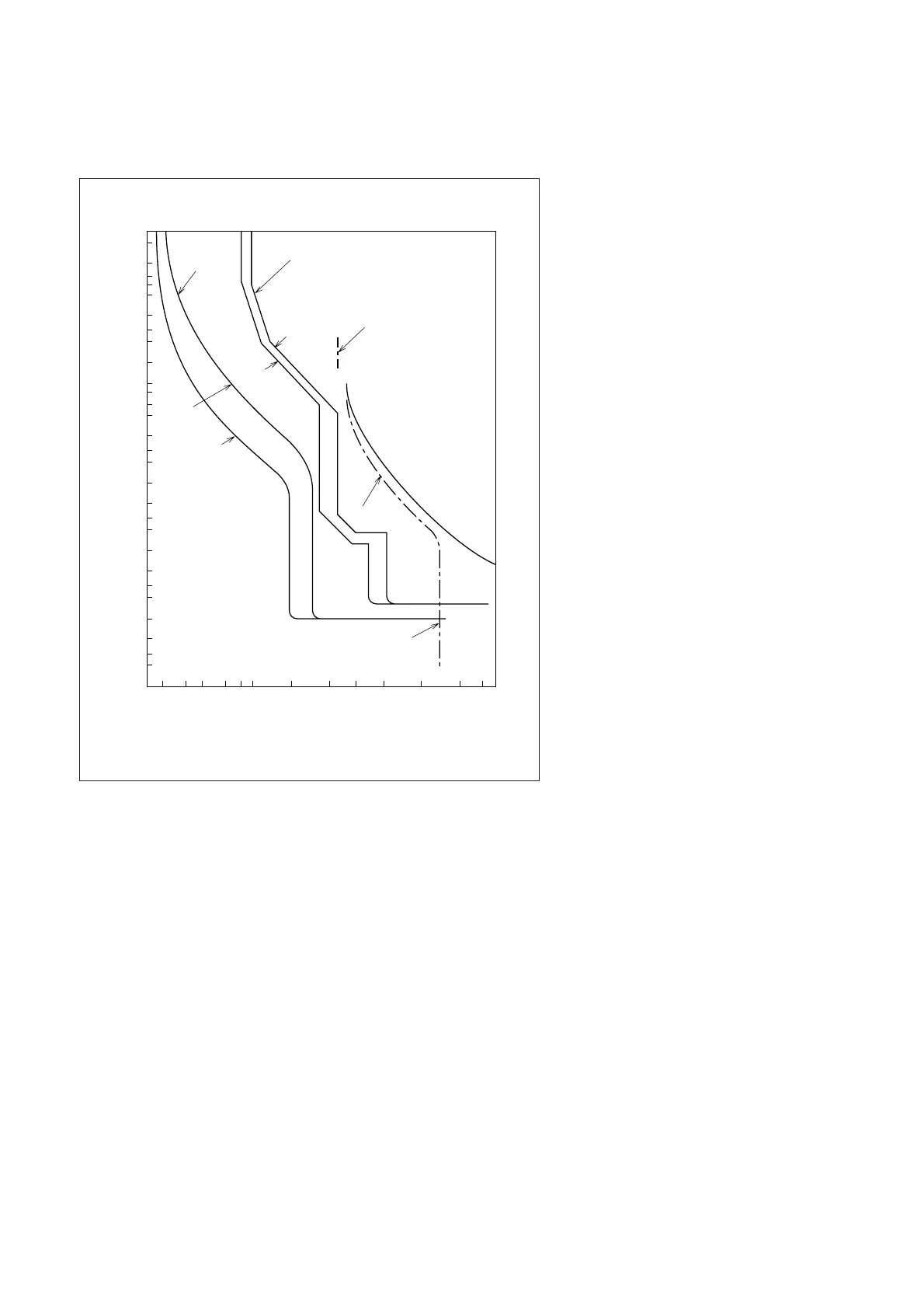
Fig. 6.27 Coordinated OCR and Electronic MCCB Characteristics
can be seen from Fig. 6.27 that the maximum trip curve
(tolerance) of the C Line units matches well with the
NF800-SEP curves, with no danger of overlap.
3 h
2
1 h
40
30
20
10 min
6
4
2
6
0.6
0.4
0.2
0.1
0.06
0.02
0.01
0.006
0.004
0.002
4
2
1 min
30
20
10 s
1 s
Time
150 300 600 1,000 4,000 10,000 40,000 80,000
200 400 800 6,000 20,000 60,0002,000
Current (A, rms)
NF800-SEP
800A setting
Max.
MOC-E tripping curve
CT ratio 150/5
Tap 5
Dial #2
Latching curve
Inst. trip
setting 30A
NF250-CP
175A
Min.
Max.
Min.
 Loading...