62
instantaneous supply voltage (V), according to the
phase angle at the instant of circuit closure. This
charge results in a large surge current. If the circuit is
closed at the peak (E
m
) of the supply voltage (V), the
surge current (i), according to transient phenomena
theory, is:
2 E
m
i =
t
2L
R
–
ε
C
4L
– R
2
2L
sin
t
C
4L
– R
2
From Fig. 7.12, the maximum value (i
m
) is:
E
m
i
m
=
R
–
ε
C
L
R
arctan
C
C
4L
– R
2
4L
– R
2
and appears at time t = t
0
where:
2L
t
0
=
R
arctan
C
C
4L
– R
2
4L
– R
2
Although V is not constant, τ
0
is extremely small, so
that V = E
m
can be assumed for the transient dura-
tion; similarly, the conduction time can be assumed
as 2τ
0
. Thus, an MCCB for use in a capacitive circuit
must have an instantaneous-trip current of greater
than i
m
x 2τ
0
.
Example: MCCB selection for a 3-phase 230V 50Hz
150 kVA capacitor circuit.
From Table 7.4, C = 0.9026 x 10
–2
(F) and I =
377(A).
The values of R and L in the circuit must be esti-
mated, and for this purpose it is assumed that the
short-circuit current is approximately 100 times the
circuit capacity – i.e., 50,000A.
Z = R
2
+ (2πfL)
2
∴ 50,000 =
3 Z
V
thus: Z = = 2.66 x 10
–3
3 x 50,000
230
since: E
m
=
obtained from their respective formulas as,
V = 188, i
m
and τ
0
can be
3
2
and assuming:
then: 2πfL = 2.60 x 10
–3
Ω
thus: R = 5.21 x 10
–4
Ω L = 8.29 x 10
–6
(H)
= 5
R
2πfL
i
m
=6200A
τ
0
= 4.27 x 10
–4
(s).
Since current-flow duration is approximately 2τ
0
,
an MCCB is selected with a latching time of 0.001
seconds at 6200A. The Type NF630-SP is suitable,
having a latching time of 0.0029 seconds at 10,000A.
Even with a shorter latching time, tripping is unlikely
under the application of the above current, but selec-
tion of an MCCB with an instantaneous-trip current of
greater than
M2
6200
= 4400A is recommended for an
adequate safety margin. Such an MCCB will be rated
at 600A. Accordingly, in this example the Type NF630-
SP, rated at 600A, is selected. Table 7.4 is a basis for
selection, but since, in cases where the short-circuit
capacity of the circuit is considerably higher than that
of the MCCB, spurious tripping due to the switching
surge may occur, it is also necessary to make calcu-
lations along the lines of the above example.
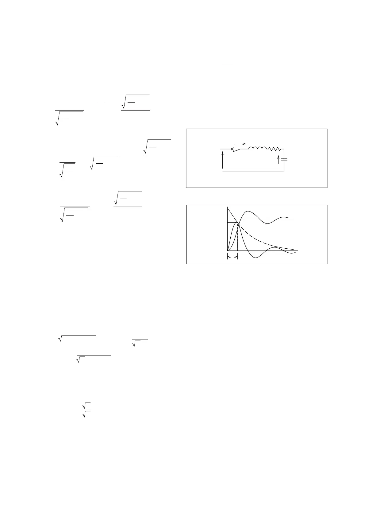
E
m
V
c
iL R
C
Fig. 7.11 PF Correction Capacitor
V
c
i
i
m
τ
o
FIg. 7.12 Currents and Voltages
7.7 MCCBs for Thyristor Circuits
Both overcurrent and overvoltage protection must be
provided for these elements. MCCBs can be used
effectively for overcurrent, although application de-
mands vary widely, and selection must be made care-
fully in each case. Overvoltage protection must be
provided separately; devices currently in use include
lightning arresters, dischargers, RC filters and oth-
ers.
1. MCCB Rated Currents
A primary factor determining the rated current of the
MCCB to be used is the question of AC-side or DC-
side installation. AC-side installation permits a lower
rating, which is a considerable advantage. Fig. 7.13
shows both AC and DC installation (MCCBs 1 and 2);
Table 7.5 gives a selection of circuit formats and cur-
rent configurations; using this table it is possible to
determine the MCCB rating for either MCCB 1 or 2,
as required. The current curve of the thyristor (aver-
age current is usually given) and the tripping curve of
the MCCB should be rechecked to ensure that there
is no possibility of overlap.
When an overcurrent is due to a fault in the load,
causing a danger of thermal destruction of the circuit
elements, either AC or DC protection is adequate,
provided the parameters are properly chosen. When
 Loading...