65
protection (MCCB1, Fig. 7.15) is presented, but the
DC-protection case (MCCB2) can be plotted in the
same way.
Region 2 in Fig. 7.17 is the area of overcurrent for
which protection is effected by the MCCB. For pro-
tection of region 1, an overload relay is effective, and
for region 2, inductance L must be relied on to limit
the fault-current rise rate, or a high-speed current-lim-
iting fuse must be used. Practical considerations, in-
cluding economy and the actual likelihood of faults in
the regions concerned, may dictate the omission of
the protective devices for regions 1 and 3, in many
cases. The lower the instantaneous-trip setting of the
MCCB, the wider the region 2 coverage becomes.
MCCB2
MCCB1
L
Smoothing inductance
R
E
Short
circuit
Load
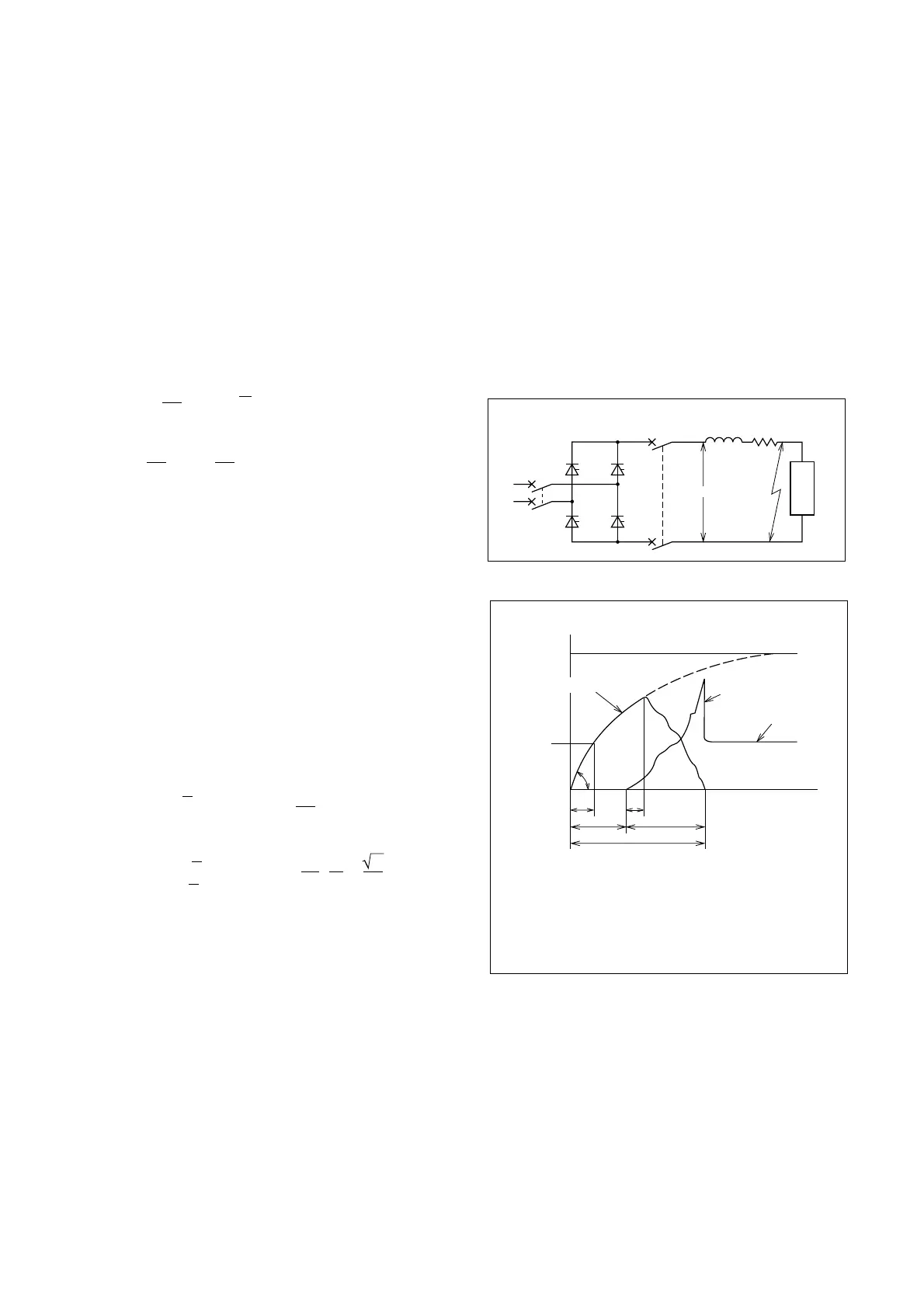
Fig. 7.15 Thyristor Short Circuit
MCCB
Short-circuit current
Trip current
q
Arc voltage
Circuit voltage
t
1
t
3
t
2
t
4
t
T
t
1
: Time to MCCB latching
t
2
: MCCB opening time
t
3
: Time from contact parting to
current peak value
t
4
: Arc duration
t
T
: Total interruption time
q : Current-rise rate
Fig. 7.16 Thyristor Short-Circuit Interruption
tates rapid interruption of the circuit. Normally, such
interruption takes place within one cycle; thus, from
the point of view of element thermal destruction, the
time integral of the current squared must be consid-
ered. Quantitatively, the permissible ei
2
dt of the ele-
ment must be greater than the ei
2
dt of the MCCB cur-
rent through interruption, converted to apply to the
element. The latter is influenced by the short-circuit
current magnitude, the interruption time, and the cur-
rent-limiting capability of the MCCB.
It is important to note that the MCCB interruption
time will be considerably influenced by the short-cir-
cuit current rise rate, di/dt, on the load side. In the
short circuit of Figs. 7.15 and 7.16, the current is:
i = (1 – ε )
E
–t
L
R
and the current rise rate di/dt is:
( )
t=0
=
dt
di
L
E
Thus, the inductance of the line, and the smoothing
inductance significantly affect di/dt. Where the poten-
tial short-circuit current is very large, the inductance
should be increased, to inhibit the rise rate and assist
the MCCB to interrupt the circuit in safe time. This is
illustrated in Fig. 7.17, for MCCB2 of Fig. 7.15.
The MCCB current during total time (t
T
) is ei
2
dt,
which, converted to the ei
2
dt applied to the circuit
element, must be within the limit specified. Having
determined the circuit constants, testing is preferable
to calculation for confirmation of this relationship.
Assuming a large current-rise rate, with an AC-side
short-circuit current i = I
ps
sin ωt, and an MCCB inter-
ruption time of one cycle, the ei
2
dt applied to the thy-
ristor is as follows:
1. For circuits I, II and III of Table 7.10:
ei
2
dt = e I
p
2
sin
2
ωtdt = I
p
2
4f
1
2f
1
0
(A
2
s)
2. For circuit IV:
ei
2
dt = 2e I
p
2
sin
2
ωtdt =
( )
+(A
2
s)
f
I
p
2
6
1
4π
3
3f
1
6f
1
where I
p
is the peak value of the element current and
f is the supply frequency.
If the ei
2
dt of the circuit element is known, the per-
missible ei
2
dt for the MCCB can be determined, us-
ing the last two equations given above. Provided that
the interruption time is not greater than one cycle, the
MCCB current will be the same as the element cur-
rent for circuits I and II, and twice that for circuits III
and IV. This means that the MCCB ei
2
dt through the
interruption time should be within twice the permis-
sible ei
2
dt of the element.
Diodes are generally stronger against overcurrent
than thyristors, and since diodes can handle larger
I
2
·t, protection is easier.
Fig. 7.17 shows the protection coordination situa-
tion of a selection of devices, plotted together with
the thyristor current-surge withstand curve. AC-side
 Loading...