78
Table 9.6 Calculation Example: 3-Phase Short-Circuit Current
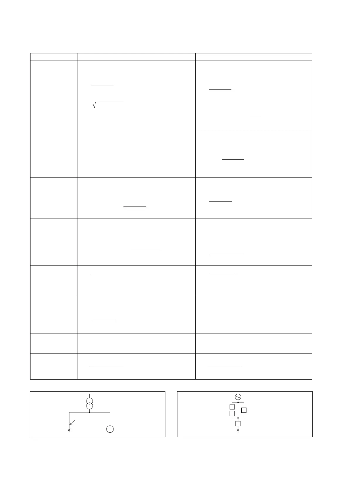
Fig. 9.6 Equivalent CircuitFig. 9.5 Circuit Configuration
Z
L
= x 100 = 0.1 (%)
1000 x 10
6
1000 x 10
3
Z
T
= (1.23 + j5.41) x
= 0.82 + j3.607 (%)
1500 x 10
3
1000 x 10
3
Z
M
= (4.11 + j24.66) x
= 3.42 + j20.55 (%)
1500 x 10
3
x 0.8
1000 x 10
3
Z
S
=
= 0.671 + j3.142 (%)
Z
L
+ Z
T
+ Z
M
(Z
L
+ Z
T
)Z
M
Ohmic method% impedance method
Power supply
impedance
Z
L
Transformer
impedance
Z
T
Motor impedance
Z
M
Total power supply
impedance
Z
S
Line impedance
Z
W
Total impedance
Z
3-phase short-circuit
symmetrical current
I
s
The supply short-circuit capacity, being unknown, is
defined as 1000MVA with X
L
/R
L
= 25.
From Eq. 13, at the 1000kVA reference capacity:
since X
L
/R
L
= 25,
The total motor capacity, being unknown, is assumed
equal to the transformer capacity, with:
%Z
M
= 25(%) X
M
/R
M
= 6
From Eq. 14, at reference capacity, 1000kVA:
From Table 9.1:
Z
T
= 1.23 + j5.41
From Eq. 14, after conversion to reference capacity,
1000kVA:
Z
W
= (0.0601 + j0.079) x 10
–3
x 10 x 100
= 0.310 + j0.408 (%)
440
2
1000 x 10
3
Multiplying the value from Table 9.2 by a wire length
of 10M, and converting to the 1000kVA reference,
from Eq. 12:
Z = Z
S
+ Z
W
= 0.981 + j3.550 = 3.683 (%)
From Eq. 2:
(R and X are calculated, per §9.3.2.)
0.1 = R
L
2
+ (25R
L
)
2
= 25.02R
L
Z
L
= R
L
+ jX
L
= 0.0040 + j0.0999 (%)
I
s
=
= 35.622 (A)
x 100
M3 x 440 x3.683
1000 x 10
3
Z
L
= = 0.0436 (Ω)
1000 x 10
6
(6600)
2
Z
L
= (1.741 + j43.525) x
2
( )
6600
440
Z
L
=
x 100 x 10
–2
x 10
3
= 0.1936 (mΩ)
1000 x 10
6
440
2
Z
T
= x (1.23 + j5.41) x 10
–2
(Ω)
= 1.2906 + j6.9825 (mΩ)
1500 x 10
3
440
2
Z
M
= x (4.11 + j24.66) x 10
–2
(Ω)
= 6.6294 + j39.7847 (mΩ)
1500 x 10
3
x 0.8
440
2
Z
S
=
= 1.299 + j6.083 (mΩ)
Z
L
+ Z
T
+ Z
M
(Z
L
+ Z
T
)Z
M
The supply short-circuit capacity, being unknown, is
defined as 1000MVA with X
L
/R
L
= 25.
From Eq. 10, the supply impedance seen from the
primary sicde:
and since X
L
/R
L
= 25: Z
L
= 1.741 + j43.525 (mΩ)
From Eq. 11, supply impedance converted to the
secondary side is:
and since
X
L
/R
L
= 25, Z
L
= 0.0069 + j0.1721 (mΩ)
Note: The supply ohmic impedance can more simply
be derived: since it is 100% at short-circuit ca-
pacity, Z
L
is obtained from Eq. 9, after percent-
age to ohmic conversion:
The total motor capacity, being unknown, is assumed
equal to the transformer capacity, with:
%Z
M
= 25(%) X
M
/R
M
= 6 Z
M
= 4.11 + j24.66
Z
M
= 4.11 + j24.66 (%)
From Eq. 9, after percentage to ohmic conversion:
Z
W
= (0.0601 + j0.079) x 10
= 0.601 + j0.79 (mΩ)
Multiplying the value from Table 9.2 by a wire length
of 10M.
Z = Z
S
+ Z
W
= 1.900 + j6.873 = 7.1307 (mΩ)
From Eq. 1
(R and X are calculated, per §9.3.2.)
= 0.00773 + j0.1934 (mΩ)
From Table 9.1:
Z
T
= 1.23 + j5.41 (%)
From Eq. 9, after percentage to ohmic conversion.
I
s
=
= 35.622 (A)
M3 x 7.1307x10
–3
440
Short-circuit
point S
3ph 50Hz
6.6kV/440V
1500kVA
10m
Wire
300mm
2
M
Short-circuit
point S
Z
L
Z
M
Z
W
Z
T
 Loading...