5 - 7 5 - 7
MELSEC-Q
5 SETTINGS AND PROCEDURES UP UNTIL OPERATION
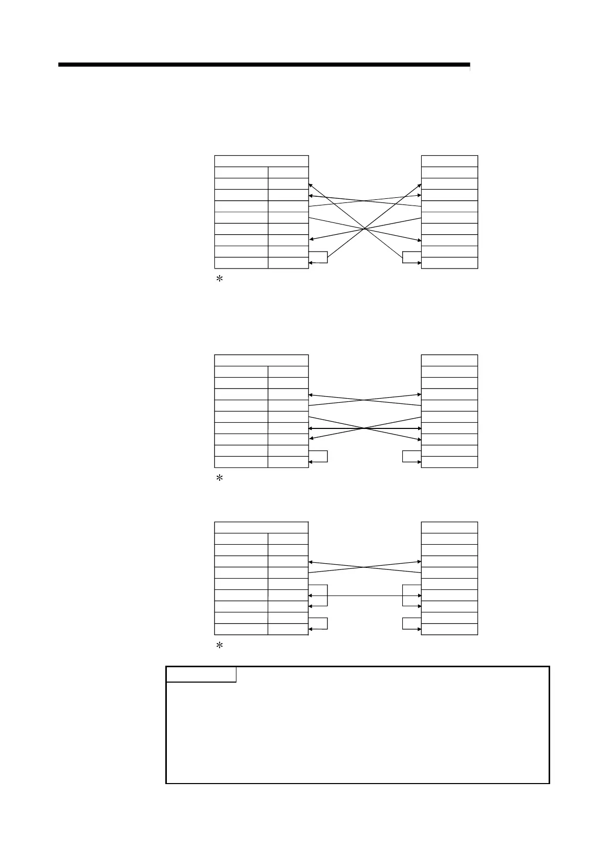
(2) Connection example
(a) Example of connection to an external device with a CD signal (pin 1) that
can be turned ON and OFF.
QD51 (-R24) Side
Signal Name
Pin No.
CD
RD(RXD)
SD(TXD)
DTR(ER)
SG
DSR(DR)
RS(RTS)
CS(CTS)
1
2
3
4
5
6
7
8
External Device Side
Signal Name
CD
RD(RXD)
SD(TXD)
DTR(ER)
DSR(DR)
RS(RTS)
CS(CTS)
SG
With the above wiring, it is possible to carry out DTR/DSR control and
DC code control.
(b) Example of connection to an external device with a CD signal (pin 1) that
cannot be turned ON and OFF.
1) Connection example 1
QD51 (-R24) Side
Signal Name
Pin No.
CD
RD(RXD)
SD(TXD)
DTR(ER)
SG
DSR(DR)
RS(RTS)
CS(CTS)
1
2
3
4
5
6
7
8
External Device Side
Signal Name
CD
RD(RXD)
SD(TXD)
DTR(ER)
DSR(DR)
RS(RTS)
CS(CTS)
SG
With the above wiring, it is possible to carry out DTR/DSR control and
DC code control.
2) Connection example 2
QD51 (-R24) Side
Signal Name
Pin No.
CD
RD(RXD)
SD(TXD)
DTR(ER)
SG
DSR(DR)
RS(RTS)
CS(CTS)
1
2
3
4
5
6
7
8
External Device Side
Signal Name
CD
RD(RXD)
SD(TXD)
DTR(ER)
DSR(DR)
RS(RTS)
CS(CTS)
SG
With the above wiring it is possible to carry out DC code control.
POINT
When it is absolutely impossible to transmit data between the programmable
controller CPU and an external device, together with a connection test, try data
communications with the wiring connections shown in the above connection
example 2.
When data communications are possible with the wiring connections shown in
connection example 2, correct the wiring connections after confirming the external
device's interface specifications.
 Loading...

