5 - 9 5 - 9
MELSEC-Q
5 SETTINGS AND PROCEDURES UP UNTIL OPERATION
(c) It is necessary to set (or connect) a terminal resistor in both terminals when
wiring.
On the QD51 (-R24) side, connect a terminal resistor (packed together with
the QD51 (-R24))in accordance with this section to match the external
device's specifications.
As for the external device side, connect or set a terminal resistor in
accordance with the external device's user's manual.
(Terminal resistors connected to the QD51(-R24) side.)
• Connect a "330Ω, 1/4 W" terminal resistor when communicating using the
RS-422 interface.
• Connect a "110Ω, 1/2 W" terminal resistor when communicating using the
RS-485 interface.
Distinguishing terminal resistors
330
Ω
110
Ω
Brown
Orange Orange
Brown Brown Brown
POINT
Including 1:n, n:1 and m:n connections, it is necessary that the device connecting
to the QD51 (-R24)'s RS-422/485 interface have a matching RS-422 or RS-485
interface.
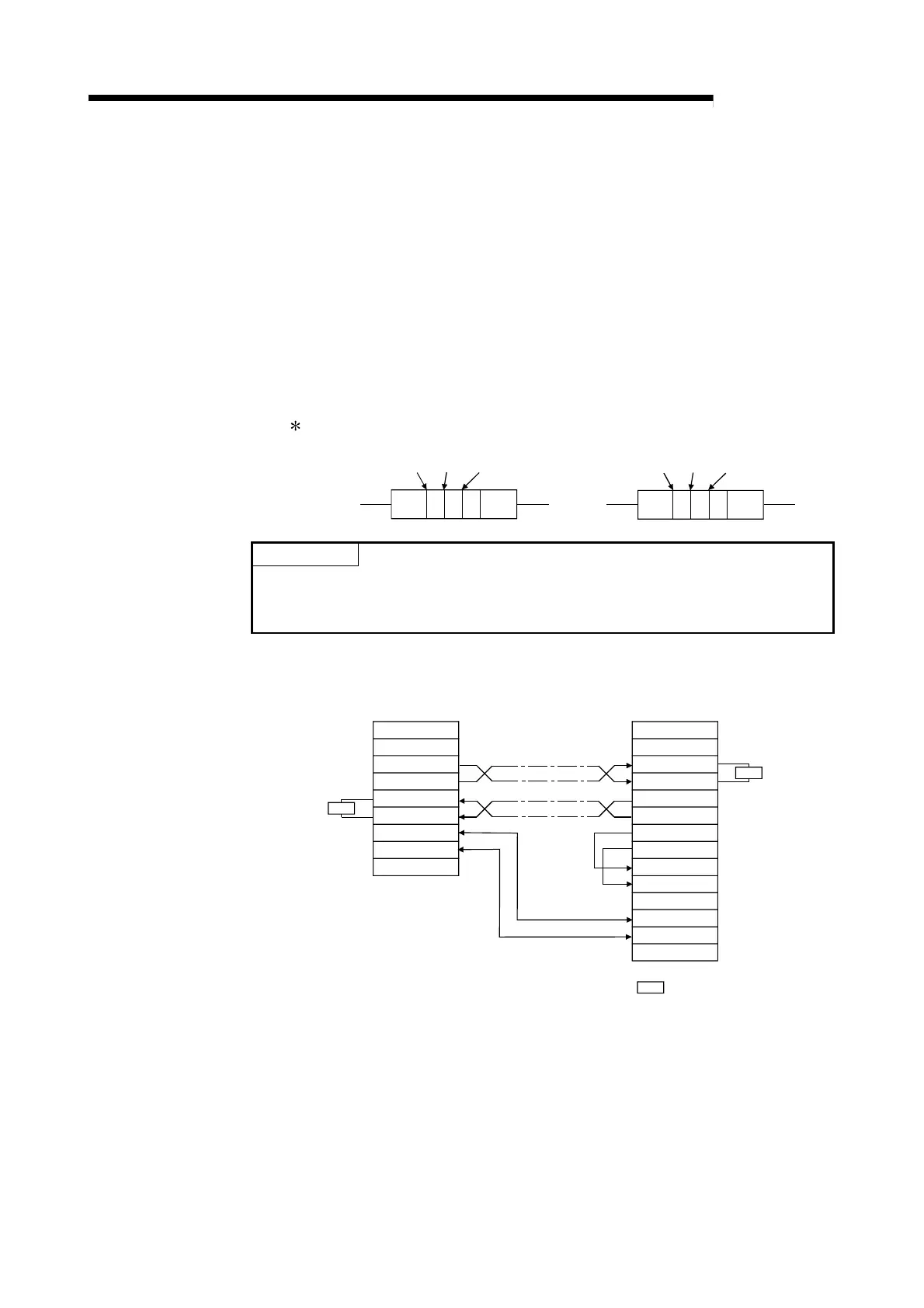
(2) Connection examples
(a) If connecting 1:1.
Terminal
Resistor
R
R
QD51 (-R24) Side
Signal Name
SDA
SDB
RDA
RDB
External Device Side
RDA
RDB
SDA
SDB
RSA
RSB
CSA
CSB
SG
FG
SG
FG
FG
Signal Name
Terminal
Resistor
Terminal Resistor
R
 Loading...

