3 - 9 3 - 9
MELSEC-Q
3 SPECIFICATIONS
POINT
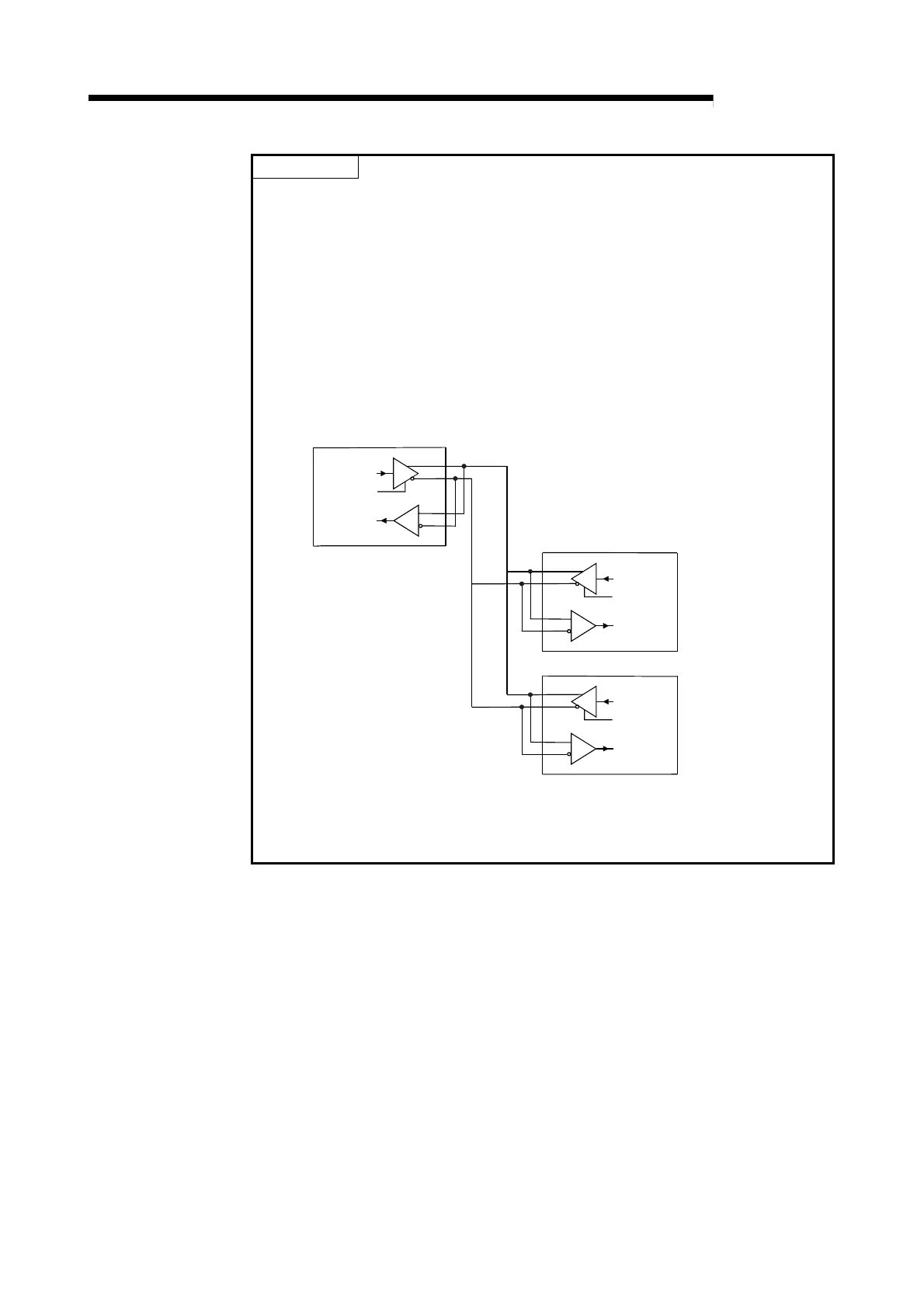
(1) When connecting each device's send signal line in system configuration of n:1
or m:n communication
Turning ON "Output Control Input" at 2 or more locations means that data are
output (sent) from the devices simultaneously.
For normal data communications, the following settings are necessary on the
opposite device side.
• Set the "Output Control Input" so that it is in the ON state only when
sending data.
• Set the "Output Control Input" so that it is in the OFF state when data are
not being sent.
The QD51-R 24 side automatically controls the output control input.
Receive
Data
Send Data
SDA
SDB
RDA
RDB
Output Control Input
Opposite Device
Receive
Data
Send Data
SDA
SDB
RDA
RDB
Output Control Input
QD51-R24
Receive
Data
Send Data
SDA
SDB
RDA
RDB
Output Control Input
Opposite Device
In the above wiring, sending and receiving are connected, the data sent by
yourself is being received by yourself. Be sure to carry out programming so
that such data are discarded by the BASIC program.
 Loading...

