3 - 8 3 - 8
MELSEC-Q
3 SPECIFICATIONS
(2) RS-422/485 Interface Operation
1) RS-422/485 Interface Configuration
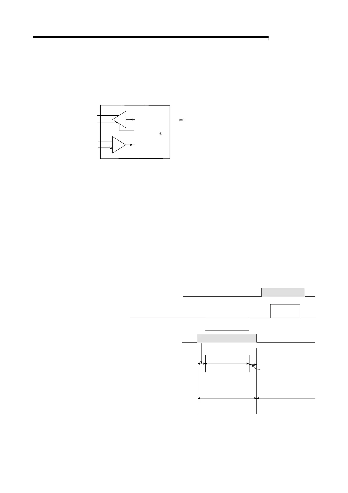
In the case of the RS-422-485 interface, the configuration of the QD51
(-R24) driver (Send) and receiver (Receive) are as shown in the
following figure.
Receive Data
Send Data
SDR
SDB
RDA
RDB
Output Control Input ( 1)
Receiver
Driver
1 The "Output Control Input" (also called the send
gate) of the driver (Send) portion in the figure at
left decides whether data from SDA or SDB are
output to an external device or not output.
2) RS-422/485 Interface Operation
In the above figure, when the "Output Control Input" is in the ON state,
it enters the low impedance state (the state in which data can be sent).
Also, when the "Output Control Input" is in the OFF state, it enters the
high impedance state (the state in which data are not being sent).
3) QD51 (-R24) send start timing and send processing end timing
• Send start timing
When data is sent, the high impedance status started by the
operation described in above 1), 2) is terminated, then a mark of
several bits is output, and the actual data is output.
• Send processing end timing
After sending of data is completed, several μs are necessary for the
Hardware gate OFF time until the send processing is ended
(changed to the high impedance state).
Mark of several bits
is output
Data sending
time range
The QD51 is in the data
reception enabled state.
Hardware Gate OFF time
“Output Control Input”
ON time range
(Low impedance state)
“Output Control Input”
OFF time range
(High impedance state)
(Output Control Input)
Opposite Device Side
QD51 (-R24) Side
(Output Control Input)
Data
Data
The QD51 is in the data
sending/reception
enabled state.
 Loading...
