207
(5) Comfort timer setting
If the timer is set at ON when the operation select switch is set at the cooling or heating, or the cooling or heating in auto mode
operation is selected, the comfort timer starts and determines the starting time of next operation based on the initial value of 15
minutes and the relationship between the room temperature at the setting time (temperature of room temperature thermistor) and
the setting temperature. (Max. 60 minutes)
Operation mode Operation start time correction value (Min.)
3 < Room temp. – Setting temp. 1 < Room temp. – Setting temp. 3 Room temp. – Setting temp. 1
At cooling
+5 No change –5
3 < Setting temp. – Room temp. 2 < Setting temp. – Room temp. 3 Setting temp. – Room temp. 2
At heating
+5 No change –5
Notes (1) At 5 minutes before the timer ON time, operation starts regardless of the temperature of the room temperature thermistor (Th
I-A).
(2) This function does not actuate when the operation select switch is set at the dehumidifying as well as the dehumidifying in the auto mode.
However, the operation of item (1) above is performed during the dehumidifying in the auto mode.
(3) During the pleasant reservation operation, both the operation lamp and timer lamp illuminate and the timer lamp goes off after expiration of the timer, ON setting
time.
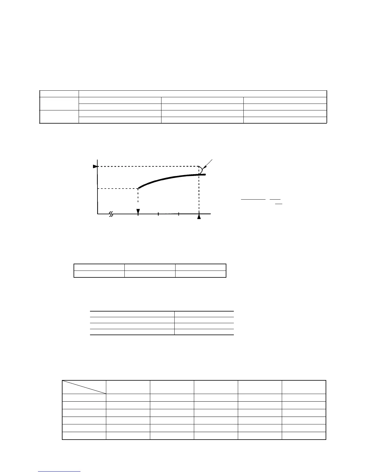
Corrects the starting time of next operation by
calculating the temperature difference.
(Example) Heating
Setting temperature
Room temperature
Operation starting time
Time
Setting time
15 min. 10 min. 5 min.
earlier earlier earlier
¡ If the difference (= Setting temperature – Room
temperature) is 4ºC, the correction value is found to be
+5 minutes from the table shown above so that the
starting time of next operation is determined as
follows:
15 min. earlier + 5 min. = 20 min. earlier
↑↑
Current operation Correction value
start time
≤
≤
≤
≤
Capacity control is within the range shown above. If demand capacity of the indoor units exceeds the maximum capac-
ity of the outdoor unit, the demand capacity will be proportionally distributed.
2) Outdoor unit speed control (28 ~ 120 rps)
(6) Cooling operation
(a) Summary
1) Capacity control
Model
Capacity
SCM45ZA
2.0 ~ 5.1 kW
SCM45YA
2.0 ~ 5.1 kW
28 rps or less
More than 28 rps, but 120 rps or less
More than 120 rps
Decision speed
28 rps
28 to 120 rps
120 rps
Indoor unit instruction total speed value
Note (1) The indoor unit instruction total speed value is the total of the values from each unit in item (b).
(b) Mode switching
Within the selected mode, the unit operates using the values shown below which were obtained by multiplying a conversion
coefficient to the indoor unit instruction speed.
Model (Indoor)
Operation Mode
Automatic
High
Medium
Low
Hi power
Econo
28 ~ 58
28 ~ 58
28 ~ 44
28 ~ 30
58
28 ~ 34
28 ~ 68
28 ~ 68
28 ~ 50
28 ~ 32
68
28 ~ 36
28 ~ 88
28 ~ 88
28 ~ 60
28 ~ 30
86
28 ~ 50
28 ~ 96
28 ~ 96
28 ~ 70
28 ~ 34
96
28 ~ 40
28 ~ 110
28 ~ 118
28 ~ 100
28 ~ 40
108
28 ~ 50
22 25 28 32 40
(rps)
 Loading...