φ15.88(5/8")(Flare)
Content
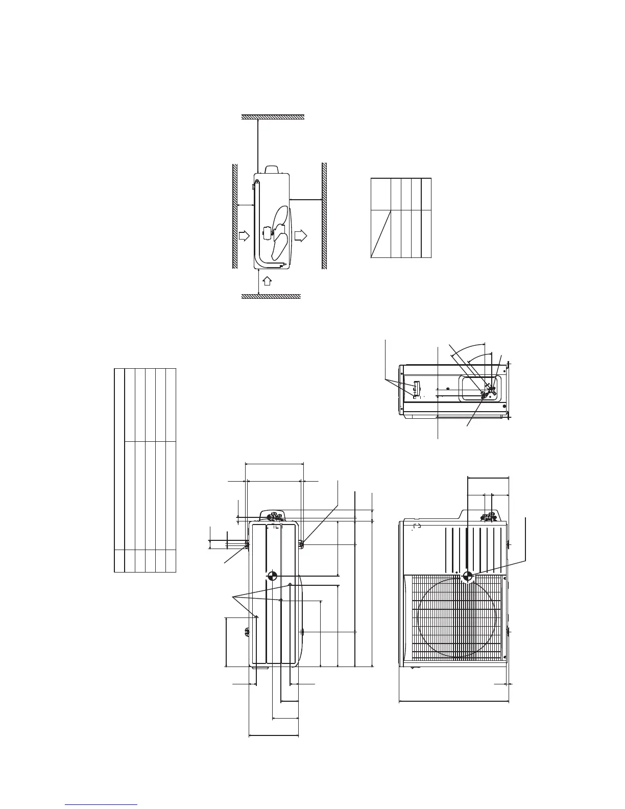
C Pipe/cable draw-out hole
D
E Anchor bolt hole
Drain discharge hole
Symbol
B
A Service valve connection(gas side)
M10×4places
φ20×3places
Service valve connection(liquid side)
φ6.35(1/4")(Flare)
Minimum installation space
Notes
.sedisruofehtnosllawybdednuorrusebtontsumtI)1(
(2) The unit must be fixed with anchor bolts. An anchor bolt must not
protrude more than 15mm.
(3) Where the unit is subject to strong winds, lay it in such
a direction that the blower outlet faces perpendicularly
to the dominant wind direction.
(4) Leave 1m or more space above the unit.
(5) A wall in front of the blower outlet must not exceed the units height.
(6) The model name label is attached on the right side of the unit.
L2
L3
L4
L1 600
100
100
Examples of
Dimensions
installation
15
640
100.3 39.7
40
40
125.4 33.3
Terminal block
43.549.6
153
476.3
203.1 510 136.9
850 65
17.9
21.9
286.4
50
12
14 312.5
340
13.5
103.2
385.9
Outlet
Intake
L3
L1
L2
Intake
Service
space
( )
L4
Open
2-16x12
240
290
320
Center of gravity
A
C
B
D
E
Unit:mm
 Loading...