Do you have a question about the Mitsubishi SRK408HENF-L3 and is the answer not in the manual?
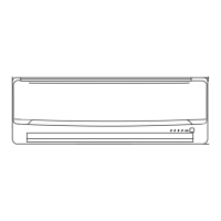
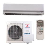
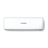
Details on the unique characteristics and capabilities of the air conditioner units.
Guide to understanding the nomenclature used for product model identification.
Detailed technical specifications, capacities, and performance data for various models.
Defines the operational boundaries and environmental conditions for optimal performance.
Provides physical measurements and mounting considerations for indoor and outdoor units.
Illustrates refrigerant flow diagrams and specifies piping requirements for installation.
Charts showing capacity correction factors based on temperature and piping length.
Diagrams and explanations of the electrical connections and components for the units.
Overview of the microcomputer's control functions and their corresponding operations.
Details on the functions and indicators of the wireless remote control unit.
Explains how to use the remote control switch for various operational modes.
Describes the function of the back-up switch for unit operation without a remote.
Details on how the unit automatically determines operation mode based on temperature.
Guidelines for adding refrigerant based on piping length and model type.
Procedures for conducting a trial run to ensure proper installation and operation.
Performance data such as pressure and current under standard operating conditions.
Guidelines for optimal placement and usage of the remote controller.
General troubleshooting steps for identifying and resolving operational issues.
Explains the meaning of indicator lamp flashing patterns for self-diagnosis.
Specific troubleshooting flows for common unit abnormalities.
Detailed flowcharts for diagnosing electronic and mechanical faults.
Guides for diagnosing issues related to temperature sensors and thermostats.
Steps to verify the functionality and reset the remote control unit.
Instructions for operating the unit via power supply ON/OFF after PCB modification.
| Type | Split System |
|---|---|
| Cooling Capacity | 4.0 kW |
| Heating Capacity | 4.5 kW |
| Energy Efficiency Ratio (EER) | 3.21 |
| Refrigerant | R32 |
| Weight (Outdoor Unit) | 31 kg |
| Noise Level (Outdoor Unit) | 50 dB |
| Power Supply | 220-240V, 50Hz |
| Coefficient of Performance (COP) | 3.61 |
| Noise Level (Indoor Unit) | 21 dB |