SERVICE MANUAL
CONTENTS
1. REFERENCE MANUAL
...................................
2
2. SAFETY PRECAUTION
...................................
3
3. PARTS NAMES AND FUNCTIONS
.................
5
4. SPECIFICATIONS
............................................
6
5. NOISE CRITERION CURVES
..........................
7
6. OUTLINES AND DIMENSIONS
........................
8
7. WIRING DIAGRAM
...........................................
9
8. REFRIGERANT SYSTEM DIAGRAM
............
10
9. TROUBLESHOOTING
....................................
11
10. FUNCTION SETTING
.....................................
25
11. SPECIAL FUNCTION
.....................................
26
12. DISASSEMBLY PROCEDURE
.......................
29
13. REMOTE CONTROLLER
...............................
33
PARTS CATALOG (TCBT011)
No. TCHT011
August 2023
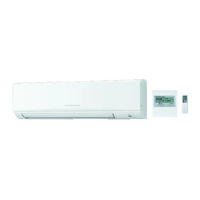
WIRED REMOTE
CONTROLLER
(Option)
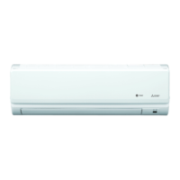
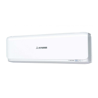
INDOOR UNIT
WIRELESS REMOTE
CONTROLLER
(Option)
MENU
ON
OFF
RETURN
SELECT
HOLD
Indoor unit
[Model Name]
TPKA0A0241KA80A
TPKA0A0301KA80A
TPKA0A0361KA80A
SPLIT-SYSTEM HEAT PUMP
/HDHVWHPDQXDOGHLQVWUXFFLRQHVKDVWDHO¿QDODQWHVGHSRQHUHQPDUFKDODXQLGDGGHDLUHDFRQGLFLRQDGRSDUD
MITSUBISHI ELECTRIC TRANE HVAC US