EasyManua.ls Logo

Mitsubishi TRUYA0361KA80NA User Manual

Mitsubishi TRUYA0361KA80NA
54 pages
To Next Page IconTo Next Page
Page #1 background imageLoading...
Page #1 background image
SERVICE MANUAL
CONTENTS
1. REFERENCE MANUAL
...................................
2
2. SAFETY PRECAUTION
...................................
3
3. PARTS NAMES AND FUNCTIONS
.................
5
4. SPECIFICATIONS
............................................
6
5. NOISE CRITERION CURVES
..........................
7
6. OUTLINES AND DIMENSIONS
........................
8
7. WIRING DIAGRAM
...........................................
9
8. REFRIGERANT SYSTEM DIAGRAM
............
10
9. TROUBLESHOOTING
....................................
11
10. FUNCTION SETTING
.....................................
25
11. SPECIAL FUNCTION
.....................................
26
12. DISASSEMBLY PROCEDURE
.......................
29
13. REMOTE CONTROLLER
...............................
33
PARTS CATALOG (TCBT011)
No. TCHT011
August 2023
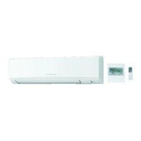
WIRED REMOTE
CONTROLLER
(Option)
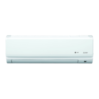
INDOOR UNIT
WIRELESS REMOTE
CONTROLLER
(Option)
MENU
ON
OFF
RETURN
SELECT
HOLD
Indoor unit
[Model Name]
TPKA0A0241KA80A
TPKA0A0301KA80A
TPKA0A0361KA80A
SPLIT-SYSTEM HEAT PUMP
/HDHVWHPDQXDOGHLQVWUXFFLRQHVKDVWDHO¿QDODQWHVGHSRQHUHQPDUFKDODXQLGDGGHDLUHDFRQGLFLRQDGRSDUD
MITSUBISHI ELECTRIC TRANE HVAC US
Questions and Answers:

Mitsubishi TRUYA0361KA80NA Specifications

General IconGeneral
Model NumberTRUYA0361KA80NA
CategoryAir Conditioner
BrandMitsubishi
Cooling Capacity36, 000 BTU/h
Heating Capacity38, 000 BTU/h
RefrigerantR410A
Heating Seasonal Performance Factor (HSPF)9.0
Operating Temperature Range (Cooling)14°F to 115°F
TypeSplit System
Power Supply208-230V, 1 Phase, 60Hz
Operating Temperature Range (Heating)75°F

Summary

SAFETY PRECAUTION

ALWAYS OBSERVE FOR SAFETY

General safety rules and precautions to follow before and during service.

CAUTIONS RELATED TO NEW REFRIGERANT

Specific safety guidelines for handling R410A refrigerant during service.

WIRING DIAGRAM

REFRIGERANT SYSTEM DIAGRAM

TROUBLESHOOTING

MALFUNCTION-DIAGNOSIS METHOD BY REMOTE CONTROLLER

Describes how to interpret error codes and indicators from the remote controller.

SELF-DIAGNOSIS ACTION TABLE

Table detailing error codes, causes, and countermeasures for self-diagnosis.

TROUBLESHOOTING OF PROBLEMS

Addresses specific issues related to LED indicators on the indoor controller board.

FUNCTION SETTING

DISASSEMBLY PROCEDURE

REMOTE CONTROLLER

ERROR INFORMATION

How to view and manage error codes and information displayed on the remote controller.

SERVICE MENU

Accessing and navigating the service menu, including password requirements.

TEST RUN

Procedures for performing test runs for cooling, heating, and vane operation.

SELF-DIAGNOSIS

Performing self-diagnosis tests and resetting error history using the remote controller.

Related product manuals