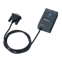
1. Introduction
No. 99MAM016B
1-
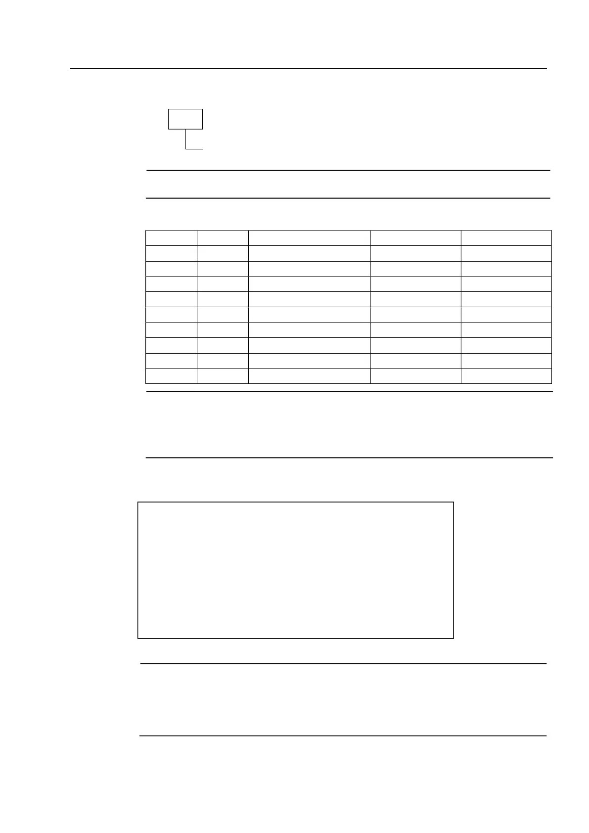
*Connector specifications
PinNo. Symbol
Signal line name
*1
Direction
*2
Power
*3
1 (N.C.) (No connect) (None)
2 RXD Received Data Output
3 TXD Transmitted Data Input
4 DTR Data Terminal Ready Input Input
5 GND Ground - Ground
6 DSR Data Set Ready Output
7 RTS Request To Send Input Input
8 CTS Clear To Send Output
9 (N.C.) (No connect) (None)
*Communication specifications
IMPORTANT
•To ensure stable data input, assign a data input interval of approximately one
second. A shorter interval may result in a data error. If an error results, an
appropriate error handling procedure must be executed in a program.
•A few seconds of power accumulation time is required before starting data input.
CAUTION
d1~d13 are respectively represent one byte.
Output signal level
Communication method
Baud rate
Bit configuration
X parameter
S parameter
Home position
: Conforms to RS-232C standard
: Full-duplex
: 2400 bps
: start bit 1 bit
data bits 8 bits
parity bit none
stop bit 1 bit
: Disables control
: Disables input/output
: DCE (modem specification)
CAUTION
*1: The signal line name is from the perspective connected to a PC.
*2: The direction of the input and output is viewed from the Input Tool.
*3: This signal line is used as a power supply of the Input Tool.
THESE SIGNAL LINES MUST BE CONNECTED.
4, Request format example
D1
CR(Return)
Or alphanumeric characters (one character)
 Loading...