Do you have a question about the Miyachi IPB-5000A-00-00 and is the answer not in the manual?
Explains the meaning of safety words and symbols like DANGER, WARNING, CAUTION.
Details guidelines for installing the power supply on a firm surface and suitable environments.
Identifies warning labels attached to the power supply and their meanings.
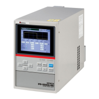
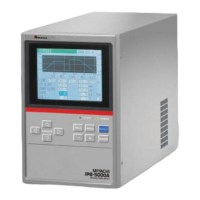
Describes the components and functions of the IPB-5000A's front control panel.
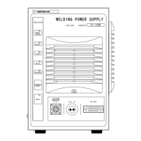
Identifies and explains the connectors and components on the rear panel of the IPB-5000A.
Provides guidelines for proper installation, including required clearances for heat release.
Illustrates the connection diagram for the IPB-5000A front and rear panels to a welding transformer.
Outlines the typical sequence of operations for using the welding power supply.
Explains how to navigate the MENU screen to access various functions and settings.
Shows connection diagrams for external signals when using PLC contacts (NPN/PNP).
Describes the contact input method for pins 1, 2, and 3.
| Model | IPB-5000A-00-00 |
|---|---|
| Category | Power Supply |
| Output Power | 5000W |
| Input Voltage | 200-240V AC |
| Input Frequency | 50/60Hz |
| Efficiency | 90% |
| Cooling Method | Forced Air |
| Operating Temperature | 0 to 40°C |
| Storage Temperature | -20 to 85°C |