Do you have a question about the Miyachi IPB-5000A and is the answer not in the manual?
Discusses general safety precautions and the meaning of warning symbols.
Details safe installation practices and environmental considerations for the equipment.
Explains the meaning and location of specific warning labels on the product.
Details functional differences between models, particularly those with displacement sensors.
Details the components and their functions on the front control panel.
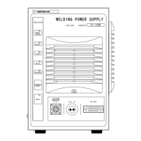
Identifies and explains the functions of connectors and components on the rear panel.
Provides guidance on proper installation clearance and location for heat dissipation.
Illustrates the overall connection diagram for external equipment and signals.
Outlines a typical operational sequence for using the welding power supply.
Explains how to access and navigate the main menu screen.
Details the process of setting up and configuring weld schedules.
Explains how to monitor welding parameters like current, voltage, and power.
Details setting criteria for judging weld quality based on monitored values.
Explains how to set up and use envelope waveforms for quality assessment.
Explains settings for prechecking weld parameters before actual welding.
Details settings for controlling weld stops and comparing weld times.
Details initial status settings for transformer, weld time, and start signal.
Illustrates connection diagrams for external equipment and signals.
Explains the function and connection of various input/output pins.
Details how schedule numbers correspond to terminal states for selection.
Illustrates the fundamental sequence of operations with timing charts and symbols.
Describes how weld schedules are determined by the start signal and timing settings.
Details the behavior of the START SIG. HOLD function under various settings.
Explains the behavior of END SIG. TIME settings and their output signals.
Describes the behavior of SOL1 and SOL2 outputs based on stage inputs.
Illustrates error or caution occurrences during the PRECHECK function.
Depicts weld sequences showing error or caution events during current supply.
Details the behavior of TRANS SCAN MODE for various settings.
Details the movement and detection of the displacement sensor during operation.
Introduces the function of communicating with external PCs for settings and monitoring.
Outlines parameters for data transmission via communication interfaces.
Details the configuration for RS-485 and RS-232C communication setups.
Describes the protocol for communication, including data formats and commands.
Lists data codes used for configuring schedules and parameters.
Provides detailed technical specifications for the welding power supply.
Lists specifications for optional accessories like cables and sensors.
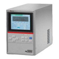
Provides a dimensional drawing of the IPB-5000A models 00-00/01/03/04.
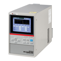
Provides a dimensional drawing of the IPB-5000A models 00-02/05.
Provides a table format for setting weld schedule parameters.
Provides a table format for setting precheck parameters.
Provides a table format for setting comparator limits for weld quality.
Provides a table format for setting control parameters like weld stop and delay time.
Provides a table format for setting various operational status parameters.
| Brand | Miyachi |
|---|---|
| Model | IPB-5000A |
| Category | Power Supply |
| Language | English |